Measure the requirement, not just the number
An inspection result depends on the feature definition, instrument, setup, environment, and decision rule. Agree these before production so a supplier and customer can reproduce the same check and understand a result close to a tolerance limit.
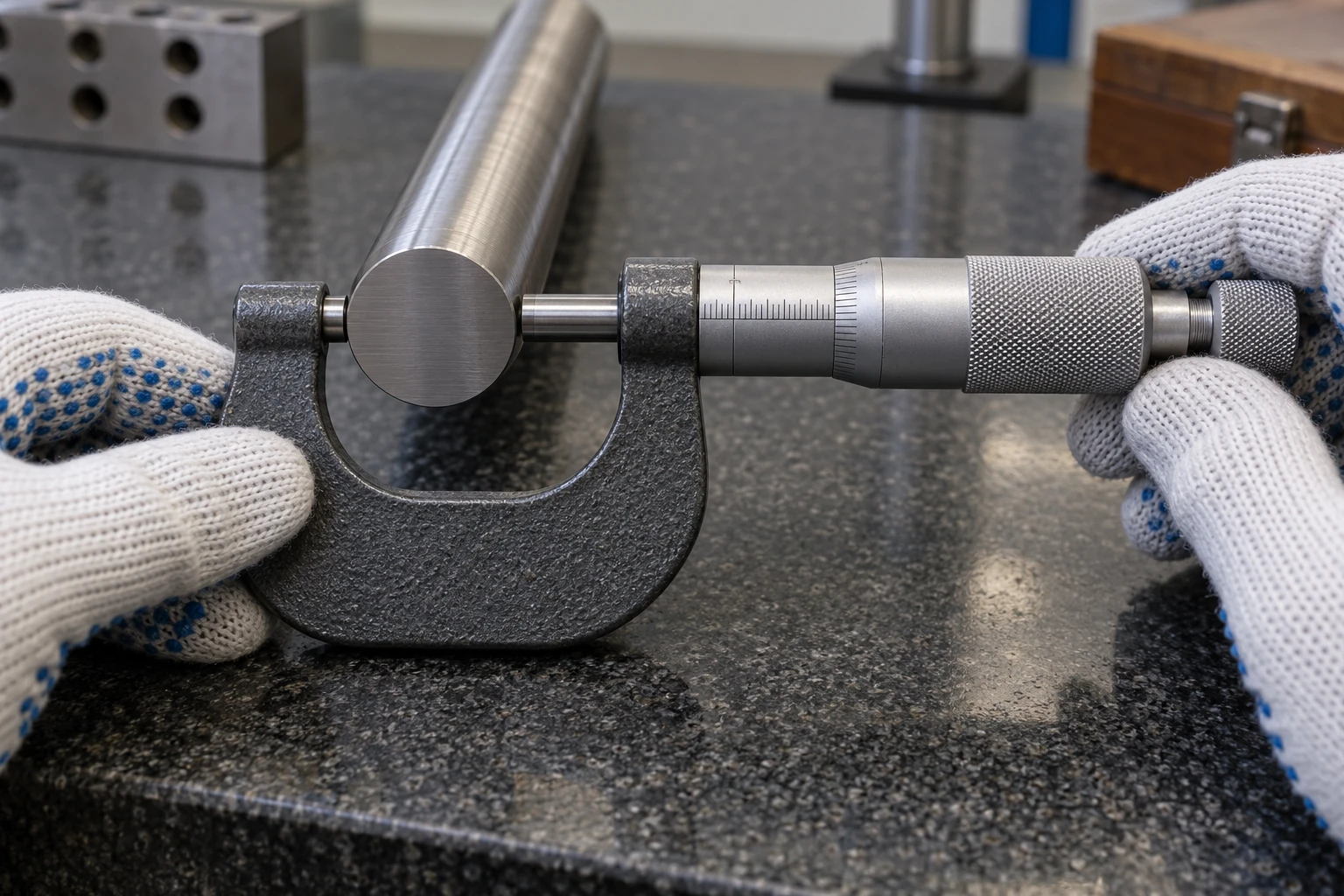
Choose an instrument for the feature
| Instrument | Typical use | Check before using |
|---|---|---|
| Caliper | Accessible external, internal, step, and depth dimensions. | Jaw condition, alignment, contact force, and whether the method suits the tolerance. |
| Micrometer | A defined size measured between appropriate contacts. | Range, anvil shape, consistent force, and access to the intended measurement location. |
| Coordinate measuring machine (CMM) | Feature positions, geometric relationships, and profiles evaluated in a coordinate system. | Datum alignment, probe access, sampling strategy, software evaluation, and task uncertainty. |
| Limit or functional gauge | An agreed go/no-go check of a defined acceptance condition. | Gauge specification, calibration, wear, operating force, and what the check does not measure. |
A caliper reading across a hole does not by itself establish roundness, and one micrometer reading does not describe a shaft along its full length. Define the locations and orientations needed to reveal the relevant variation. A specialized bore gauge, height instrument, thread gauge, or surface instrument may be the better tool for a particular requirement.
Resolution is not measurement uncertainty
Instrument resolution describes the smallest change in the measured quantity that produces a perceptible change in the indication. Accuracy concerns closeness to the true value of that quantity; suitable reference values are used in practice to assess measurement error. Repeatability compares results over a short period using the same procedure, operators, measuring system, location and operating conditions. Measurement uncertainty is a non-negative parameter describing the dispersion of values attributed to the quantity being measured. It is not simply the span between the largest and smallest repeat readings. State whether a reported uncertainty is standard or expanded, and give the coverage factor or coverage probability as applicable. More displayed digits do not remove errors from contact, alignment, temperature or calibration.
Reference: NPL Good Practice Guide 40, terminology and uncertainty
JCGM VIM: measurement accuracy · JCGM VIM: repeatability conditions · JCGM VIM: measurement uncertainty
Ask whether the complete measurement method is suitable for the tolerance, especially near an acceptance boundary. Agree how uncertainty affects the pass/fail decision and how disputed results will be rechecked. Record the instrument identity and calibration status; a calibration certificate supports traceability but does not validate every future setup or operator technique.
Reference: Mitutoyo understanding CMM specifications and calibration
Control datums, contact, and restraint
Use the drawing's datum system and stated standard. Measuring a hole from an arbitrary outside edge can produce a different result from evaluating its position relative to the specified datum features. For CMM work, agree alignment and feature evaluation, along with sufficient point coverage for the feature being inspected. A convenient best fit may answer a different question.
Remove loose contamination and confirm whether burr removal is permitted before inspection. Burrs, roughness, coatings, and contact-tip geometry can affect the surface actually sampled. Do not silently polish a nonconforming feature into compliance. Record whether dimensions apply before or after finishing and retain the specified surface condition during acceptance checks.
Thin parts can change shape under clamp or probe force. Specify free-state inspection or the required restrained condition, including support locations and clamping method. A fixture should locate the part reproducibly with only the necessary holding force. If the component is accepted in its assembled condition, define that condition rather than improvising it at inspection.
Source: Renishaw metrology fixturing technical specification
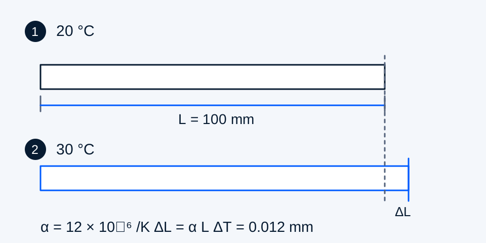
Example: temperature changes the dimension
The standard reference temperature for dimensional measurement is 20 °C. Away from that temperature, expansion corrections and their uncertainty can matter. Allow the workpiece and equipment to stabilize; a part brought directly from machining, sunlight, or transport may not represent the inspection environment. Measuring room air alone does not establish the part's temperature.
Source: NIST uncertainty in dimensional measurements at nonstandard temperatures
Agree a report that supports acceptance
Before quotation, agree the drawing revision, numbered characteristics, nominal values and limits, sampling quantity, actual results, units, instrument or method, datum setup, environmental conditions where relevant, and acceptance rule. Identify each inspected part or lot. State whether the report covers every part, a first article, or a sample; these are different deliverables.
When results disagree, compare the definition and setup before adjusting the process. Recheck revision, cleanliness, temperature, contact location, restraint, and calculation method. Preserve the original readings and identify the agreed repeat measurement so the record explains the decision instead of merely replacing an inconvenient number.