Holes, threads and tolerances
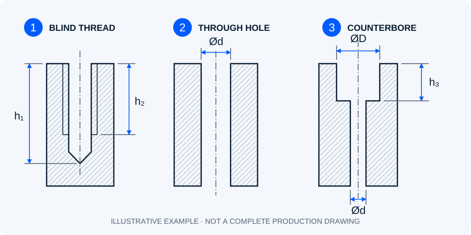
Specify the feature that the assembly actually needs. Hole depth, full-thread engagement, size, position and inspection conditions describe different requirements.
Holes and threads: specify the usable feature
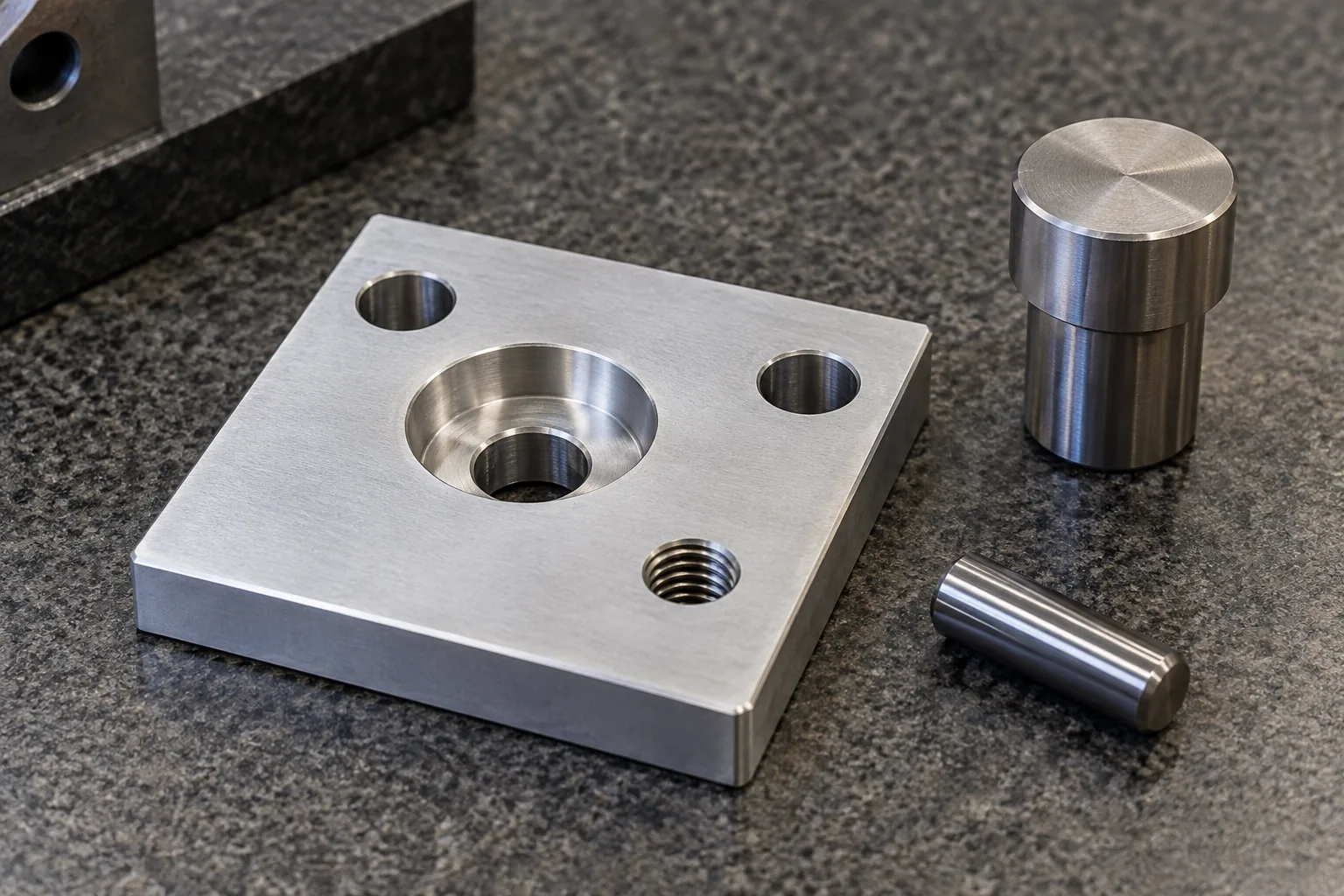
For holes, give diameter, depth, location, fit and surface requirements. Distinguish through holes from blind holes, and usable cylindrical depth from the drill-tip space. Angled entries, angled exits and intersecting holes can affect tool choice and chip removal. A drilled clearance hole and a locating bore serve different functions; explain the assembly need so the production method can be selected accordingly.
For threads, specify the standard, nominal diameter, pitch, tolerance class and minimum full-thread depth. State whether a coating applies inside the thread. Blind-hole drill depth, thread depth and bottom clearance need coordinated planning. Thread milling may be useful near a shoulder or blind bottom, on thin-walled parts or where tap-breakage risk matters. Avoid assuming that a longer thread always creates a better joint; required engagement depends on loads and materials.
Sandvik Coromant: hole geometry, quality and drilling choices
Sandvik Coromant: thread milling applications
Tolerances, datums and inspection: describe the assembly
A size tolerance does not describe every relationship that makes an assembly work. A bore can have the correct diameter while its axis is in the wrong position. Choose datum features that represent how the part seats and locates in use, then specify the necessary form, orientation and location controls. Identify the drawing convention and applicable edition so everyone interprets the requirements consistently.
Concentrate demanding requirements on features that need them. Agree the measurement method, access, datum establishment, part condition and reporting before production. Instrument resolution alone does not establish measurement uncertainty. Temperature also matters when tolerances are small: NIST describes the effects of temperature and thermal-expansion uncertainty relative to the 20 °C dimensional reference temperature. State whether acceptance is before or after coating and thermal processing.