Geometry, rigidity and workholding
Consider tool access and how the part is supported throughout the cut, not only the final shape. These design reviews connect thin features and deep pockets to fixturing, distortion and vibration.
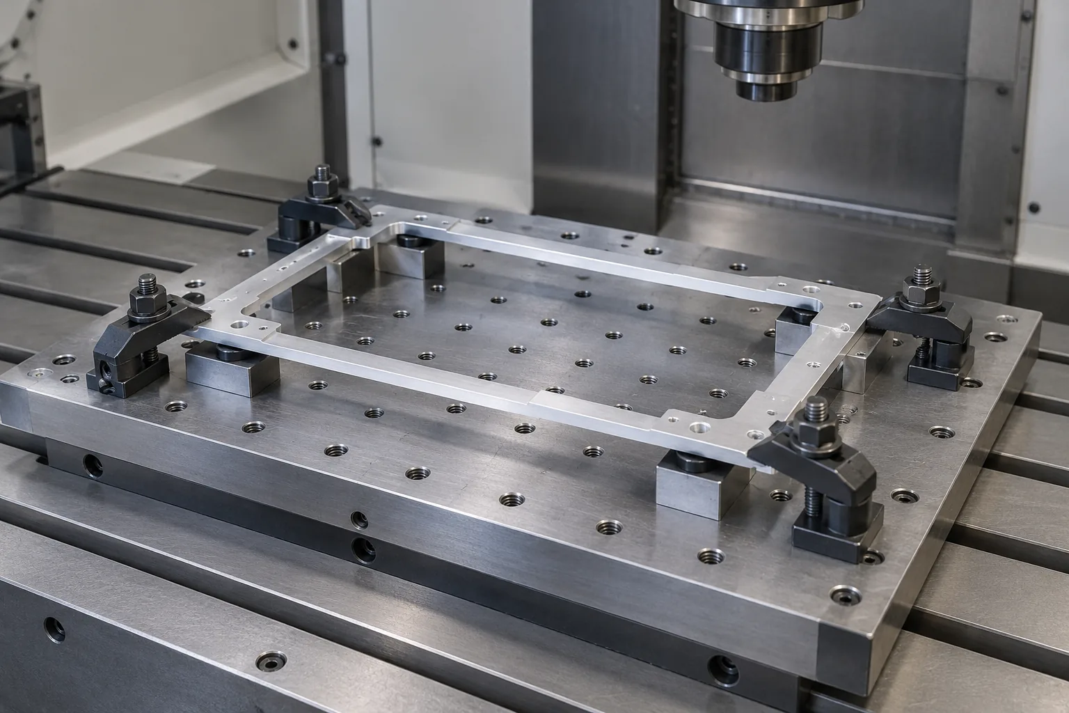
Thin walls and floors: consider support as well as thickness
Wall height, thickness, unsupported length and material all influence how a feature responds during cutting. A tall isolated wall behaves differently from a short wall tied into surrounding ribs. Thin floors can also bend under cutting or clamping loads. There is no single minimum wall thickness that establishes whether every material and geometry can be machined successfully.
Retaining material for support during roughing and approaching the final section in stages can help control deflection. Sandvik describes alternating sides and staged strategies according to wall proportions. These are process-planning approaches, not design acceptance limits. Ask whether a rib, shorter wall, thicker base or temporary support feature is compatible with the part function and final assembly.

Internal radii and pockets: leave room for the cutter
A rotating end mill leaves a radius in an internal vertical corner. Making that radius smaller usually changes the required tool diameter, reach or number of operations. When the cutter nearly fills a corner, engagement increases and the cut can become less stable. Give internal corners the largest radius that still provides clearance for the mating component and preserves required strength.
Review pocket depth, width, floor thickness and corner radius together. A narrow deep pocket can combine poor access, a slender tool and difficult chip removal. Where the function allows, consider a shallower pocket, larger corner radii, an opening through one side or an assembly of simpler components. A square mating tab may instead accept corner reliefs. Any departure from the released drawing needs agreement.

Part size and fixturing: plan how the work is held
Final length, width and height are only part of a size review. The starting stock, fixture, cutting tool, holder and approach movements also need space. A part fitting within a nominal machine travel does not establish that every surface is reachable. Small parts may need dedicated handling or support just as large parts may need several setups. Identify surfaces that can be used for holding.
Mark faces that cannot carry clamp marks, sacrificial material that may be removed later, and features that must stay related across setups. Ask how the final operation will hold the part once most stock has gone. For rotating fixtures, review the combined moving envelope and tool clearance. Simulation must represent the actual stock, holder and fixture rather than only the finished model.
Warpage and residual stress: define the free condition
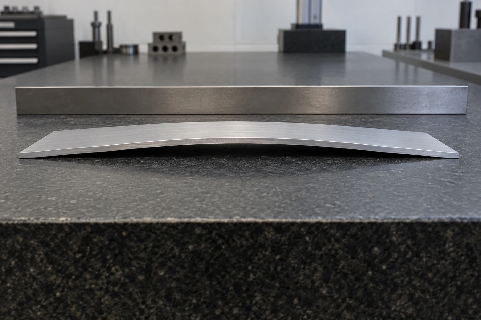
A part can look flat while held and change shape after release. Elastic bending under a clamp is different from distortion associated with residual stress and material removal. Wrought stock can contain residual stress from earlier processing; removing material changes the remaining balance. NIST research on aluminum bars illustrates why stock condition and the location of a part within the stock can matter.
Flag broad thin plates, heavy one-sided pocketing and tight flatness requirements early. Discuss suitable stock condition, staged removal, support and any necessary thermal processing with the manufacturer. These choices have material, schedule and cost implications; no single treatment guarantees a distortion-free part. State whether inspection is in the free condition, on defined supports or under a specified assembly restraint, and agree that condition before setting an acceptance value.
NIST: aluminum residual stress and machining distortion, printed pages 34–35
Chatter and tool reach: avoid unnecessary slenderness
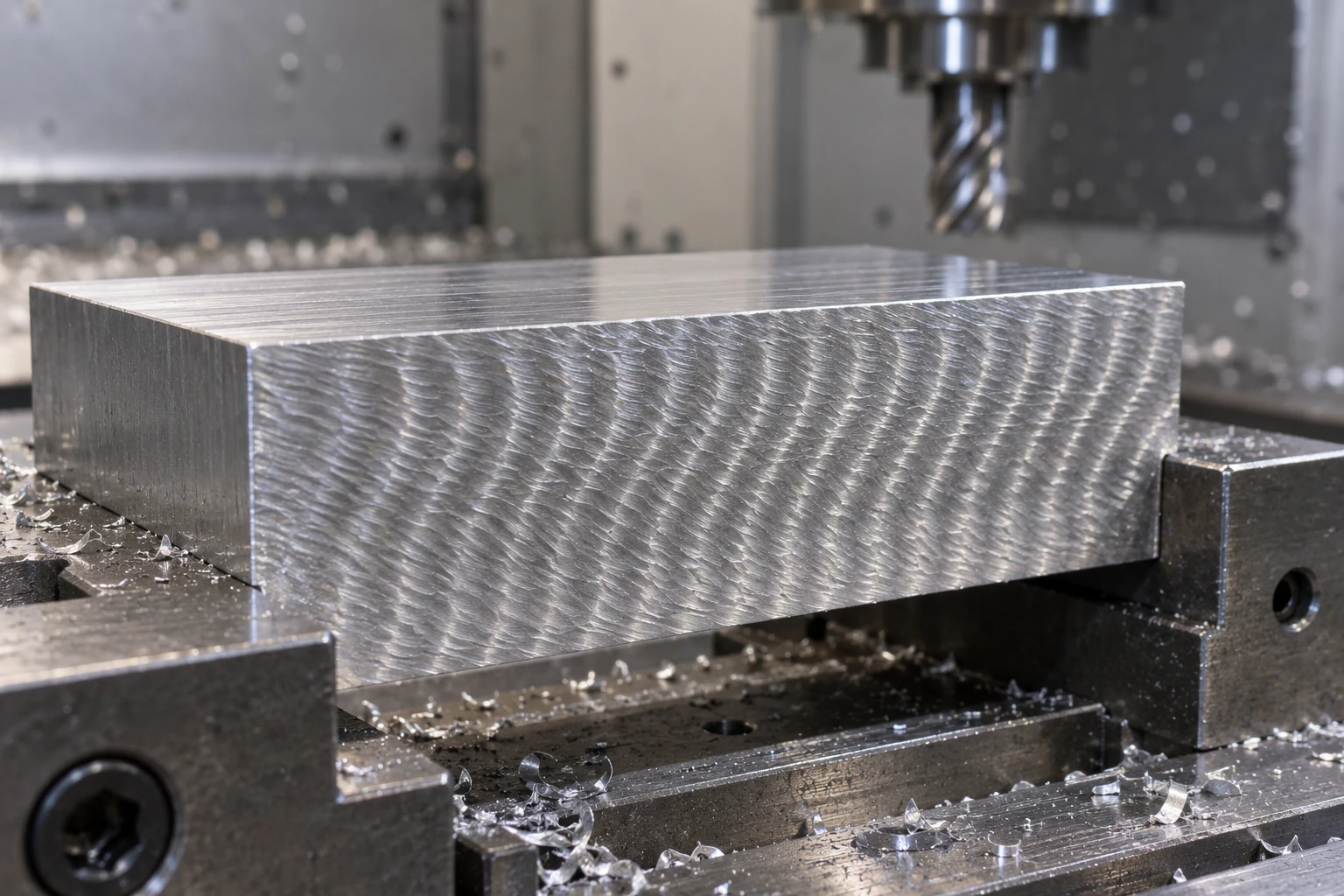
Chatter can involve the cutter, holder, machine, workpiece or fixture. It may leave repeated marks and interfere with surface quality or dimensional control. A long slender tool and an unsupported wall create different sources of flexibility. Changing speed alone is not a universal cure. The design contribution is to avoid unnecessary reach, abrupt access restrictions and unsupported features where the function permits.
Ask whether an opening can be enlarged, a deep feature approached from another face, or a narrow detail separated from the main roughing operation. The manufacturer must coordinate tool length, holding, engagement and cutting conditions. Do not prescribe a universal cutting recipe on a drawing. If a surface has a functional texture requirement, identify it explicitly so cosmetic tool marks are not confused with acceptance criteria.