CNC feeds and speeds: calculate, then verify
Connect cutting speed, spindle speed and feed with the actual tool, material, engagement and machine limits. Worked metric examples show how to keep units and assumptions consistent.
Start with the exact tool and operation
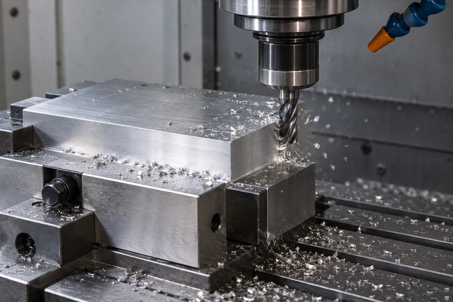
A useful cutting plan starts with the material grade and condition, tool part number, substrate, coating and operation. Obtain the tool manufacturer’s starting data for that combination. A value for side milling cannot automatically become a slotting or drilling value. Check whether the recommendation assumes flood coolant, internal coolant, air or dry cutting, and whether it specifies a particular engagement.
Sandvik Coromant: product-specific cutting data and tool selection
Define the quantities before calculating
| Quantity | Meaning and unit |
|---|---|
| Vc | Cutting speed at the cutting diameter, m/min |
| D | Effective cutting diameter, mm; for turning use workpiece diameter at the cut |
| n | Spindle speed, rpm (revolutions per minute) |
| fz / fn | Feed per tooth, mm/tooth / feed per revolution, mm/rev |
| vf / zc | Linear feed, mm/min / effective cutting teeth per revolution |
| ap / ae | Axial depth / radial width of cut in milling, mm |
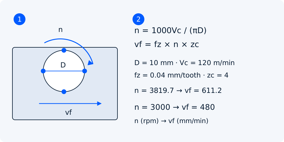
Keep millimetres and metres separate: the factor 1000 converts the cutting-speed units. The spindle relationship is n = 1000 × Vc / (π × D); reversing it gives Vc = π × D × n / 1000. Use the effective diameter at the cutting depth, rather than blindly using the tool’s largest catalog diameter.
Sandvik Coromant: milling quantities and effective cutting diameter
Milling: feed per tooth and an RPM cap
For milling, vf = fz × n × zc. Use the manufacturer’s effective tooth count for the cutter configuration; do not substitute the number of teeth simultaneously touching the part. For an ordinary four-flute end mill with four effective edges, zc is four. Special staggered or multi-row cutters need the supplier’s definition. Feed per tooth and maximum chip thickness are related, but are not always equal.
Keeping 611.2 mm/min after that speed reduction would raise fz to about 0.0509 mm/tooth. A feed override can therefore change chip loading as well as cycle time. Round the programmed values sensibly, then calculate back from the values actually entered. An RPM cap is a limit, not proof that the resulting lower cutting speed suits the tool.
Sandvik Coromant: metric milling formula sheet
Engagement changes the cutting load
Record ap and ae alongside speed and feed. A full-width slot and a light side cut can share RPM and programmed fz while imposing very different loads and chip-clearance demands. At low radial engagement, radial chip thinning can make the maximum chip thinner than the programmed feed per tooth. Entering angle and rounded cutting edges can also change the relationship.
Use the tool maker’s engagement correction or a verified CAM model. Do not apply a generic chip-thinning multiplier twice if the supplier or CAM system already compensates. Review corners, entry moves and narrow passages where engagement increases. A feed calculated for a straight light side cut does not automatically remain suitable when the tool encounters a corner.
Drilling: feed per revolution
Drilling data commonly specifies fn in mm/rev. Calculate vf = fn × n; do not multiply the stated feed per revolution by the drill’s flute count. Confirm that the control or CAM output expects mm/min or mm/rev. Hole depth, entry angle, coolant delivery and chip evacuation still determine whether a proposed drilling cycle is suitable.
Turning: workpiece diameter and constant surface speed
For turning, D is the workpiece diameter at the cutting location, not the insert nose radius. At Vc = 150 m/min and D = 50 mm, n is 954.9 rpm. At D = 20 mm, the same target requires 2387.3 rpm. A 2000 rpm clamp limits actual cutting speed at 20 mm to 125.7 m/min.
Constant surface speed increases RPM as the cutting diameter shrinks. Set a verified maximum speed that respects the machine, chuck, jaws, workpiece balance and holding arrangement. Haas documents G96 for constant surface speed and G50 for its speed limit; other controls must be checked against their own manuals. Confirm feed mode independently: a distance per revolution is not a distance per minute.
Verify the complete setup and record the result
Check the available torque and power at the selected RPM, feed-axis capability, tool and holder speed ratings, overhang, runout, clearance and fixture support. Observe a controlled first cut for chip evacuation, vibration, spindle load and dimensional drift. Stop for an unstable condition. Change one variable at a time and retain the tool code, material condition, ap, ae, coolant method and wear observations so the next trial has a useful baseline.
Sandvik Coromant: machine and setup considerations for milling