CNC cutting tools: select the whole cutting system
Match tool material, geometry, coating and holding to the workpiece and operation. A useful selection balances edge strength, chip space, access and a stable cutting process.
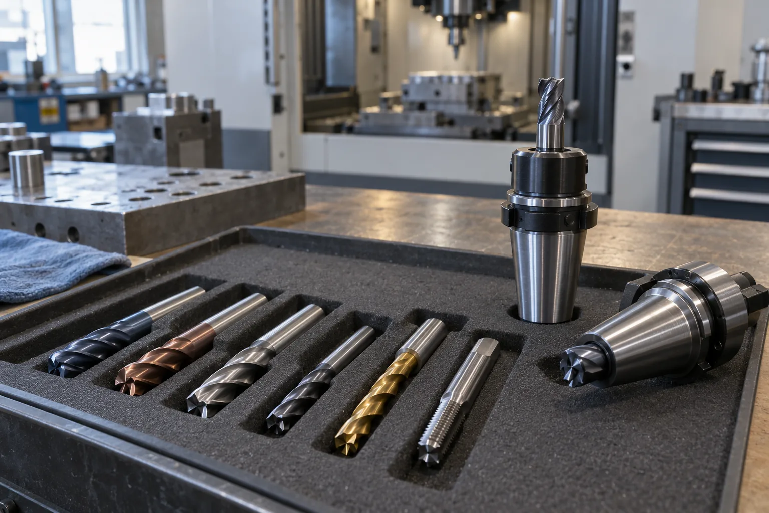
Choose for a defined operation
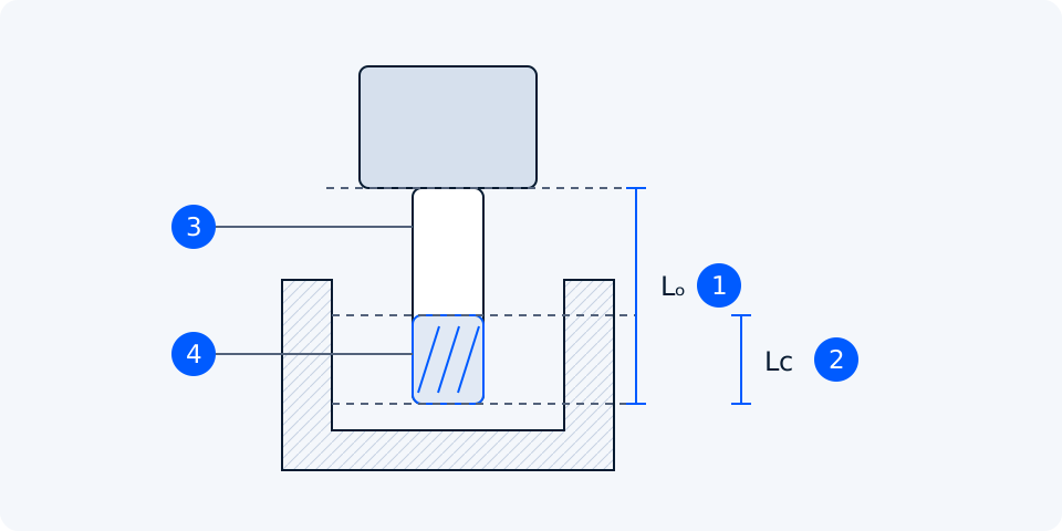
Start with material grade, hardness or temper, feature dimensions and required finish. Separate roughing, finishing, slotting, drilling and profiling requirements. Confirm the tool’s permitted entry method: an end mill that cuts on its periphery is not automatically suitable for plunging. Record diameter, usable cutting length, neck clearance and holder envelope before considering a faster cutting recipe.
Carbide and high-speed steel
Carbide generally offers greater stiffness and hot wear resistance, supporting productive cutting in a rigid setup. It is also sensitive to impact and poor alignment. High-speed steel, including cobalt-alloyed HSS grades, can offer useful toughness where flexibility or interrupted loading matters, usually at lower cutting speeds. Neither label determines the whole result: substrate grade, edge preparation, diameter and application still matter.
Geometry and coating follow the material
For aluminium, a sharp edge, generous chip space and a surface that discourages adhesion can help prevent built-up edge. Harvey describes TiB2 as one option with low affinity for aluminium. This is a material-specific choice, not a rule that every coated tool suits aluminium. For steels and harder materials, select the maker’s matching substrate, coating and edge-strength recommendation rather than choosing by coating colour.
Harvey Performance: TiB2 coating for aluminium applications
Stainless steel, titanium and heat-resistant alloys each require their own tool family and data. A stronger honed edge can resist damage but may raise cutting forces; a keen edge can lower forces but sacrifice strength. Ask how the geometry manages the actual material’s adhesion, heat and work-hardening behaviour. A coating cannot compensate for unsuitable geometry, chatter or recutting trapped chips.
Flute count is also a chip-space decision
More flutes can support a higher table feed at the same RPM and feed per tooth, but leave less space for chips in a comparable diameter. Fewer flutes can help with bulky chips and full-width slots. Light radial finishing permits different choices from deep slotting. Use the specified effective tooth count in feed calculations; do not increase feed simply because another cutter has more flutes.
Runout, overhang and holder clearance
Tool runout makes edge loading unequal, especially when the intended chip load is small. Inspect the clean tool shank, collet, holder and spindle interface, and measure the assembled system using an appropriate method. Keep overhang only as long as access requires. Extra flute length is not a substitute for a relieved neck; check that non-cutting portions and the holder clear the part throughout the path.
Harvey Performance: measuring and reducing assembled tool runout
Ball nose tools need the effective diameter
On a ball nose, contact near the tip occurs at a smaller diameter than the nominal tool size. Surface speed approaches zero at the centre. Use the effective diameter for the actual contact position and cutting depth when setting RPM. Surface slope, tool tilt and path direction change that contact. Check the CAM strategy and supplier guidance rather than increasing RPM without checking the tool and holder limits.
Climb or conventional milling?
Climb milling produces a chip that generally thins toward exit in peripheral cutting. It is often preferred where the machine, fixture and workpiece allow it. Backlash can permit the cutter to pull into the work unexpectedly; conventional milling may be appropriate on equipment that cannot control this movement. Review machine condition and cutting forces before selecting a direction. A CAM default is not evidence of mechanical suitability.
Plan chip removal and read the wear
Choose coolant or dry machining from the tool’s application guidance. Lubrication, chip removal and thermal cycling all matter; intermittent or poorly directed coolant can create problems. Check delivery into the actual cutting zone, especially in deep pockets and holes. Follow the material and machine requirements for dust, mist and chip management.
Sandvik Coromant: coolant and temperature cycling in milling
| Observation | Investigate before changing settings |
|---|---|
| Uneven edge wear | Runout, seating and uneven engagement |
| Built-up material on the edge | Material adhesion, geometry, lubrication and cutting data |
| Chipping or rapid failure | Stability, entry load, trapped chips and tool suitability |
Stop for sudden damage or instability. Photograph the edge, note cutting time and retain the exact tool code and settings. Compare symptoms with the tool maker’s troubleshooting guide, then change one cause at a time. Replace damaged tooling before evaluating surface finish or dimensions.
Sandvik Coromant: examples of wear mechanisms and troubleshooting