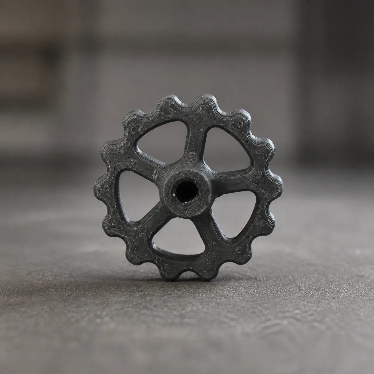
From concept to a working part.
MALIEV specializes in prototype development and reverse engineering. We create new parts from ideas and reconstruct designs from existing parts to make replacements, improve function and develop products further.
Established in 2018
Nonthaburi, Thailand
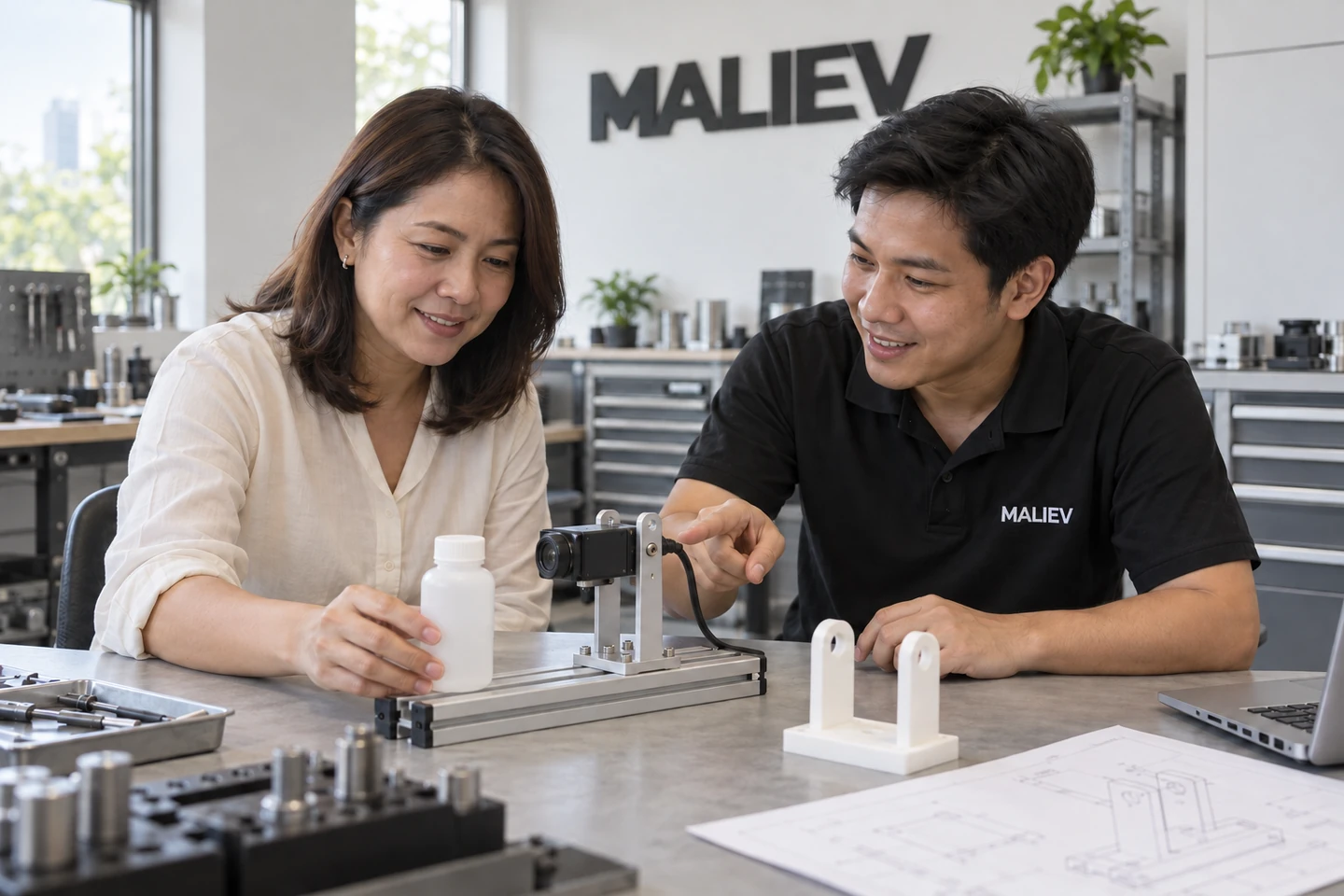
One bracket. From idea to production line.
An illustrative camera-mount project for inspecting bottles: define the requirements, develop the bracket, test variations and prepare the final design for use.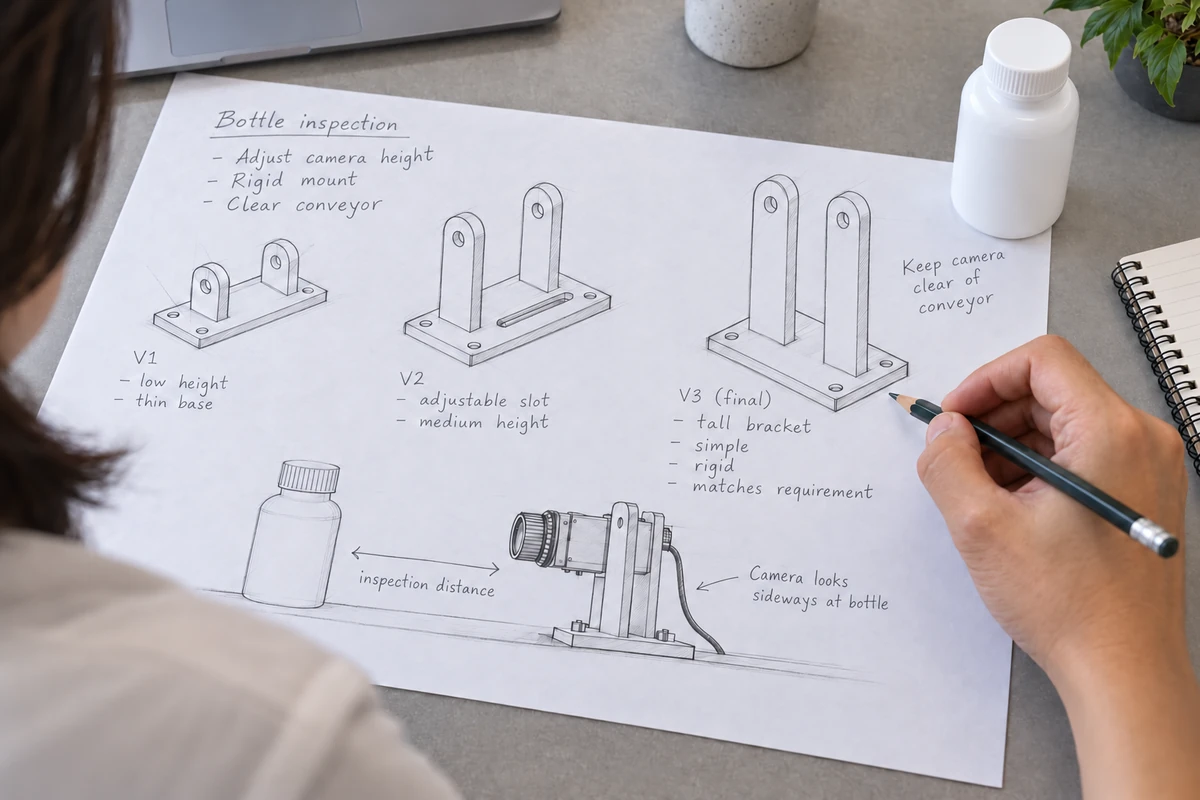
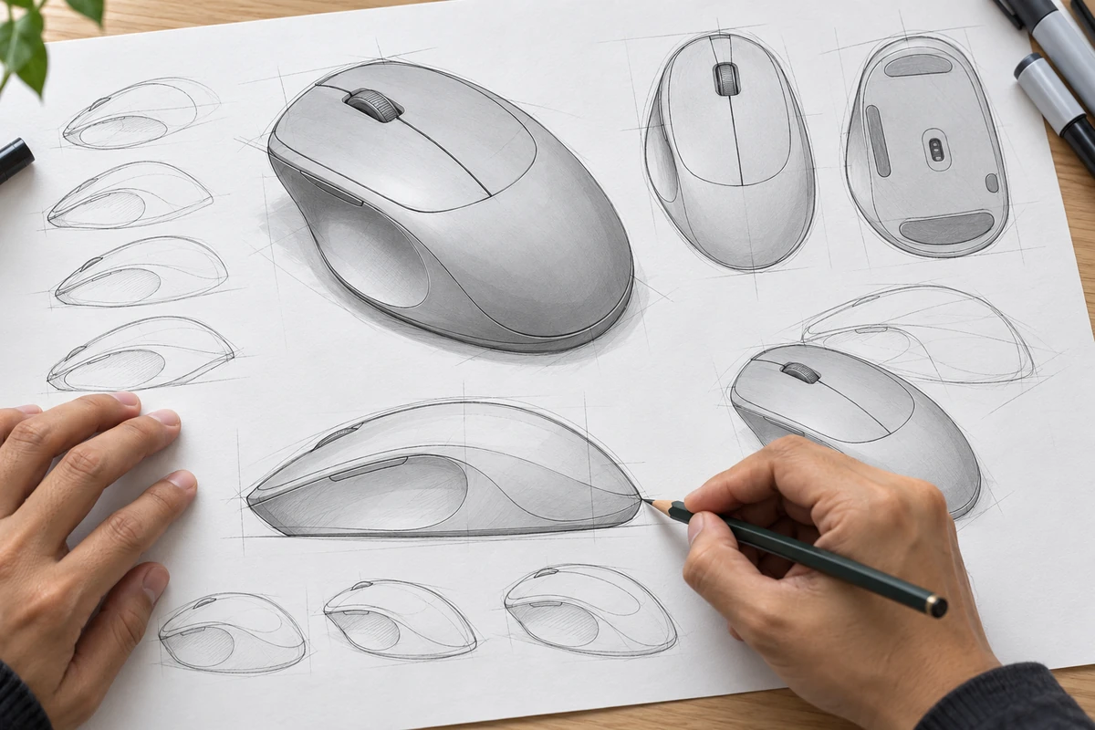
01 · Idea & sketch
Sketch bracket alternatives around the bottle, camera position and conveyor clearance. Record the basic requirements before developing CAD.
Discuss your idea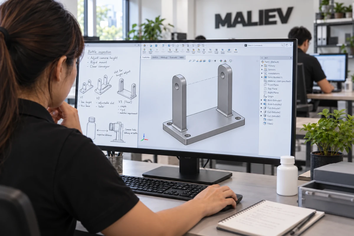
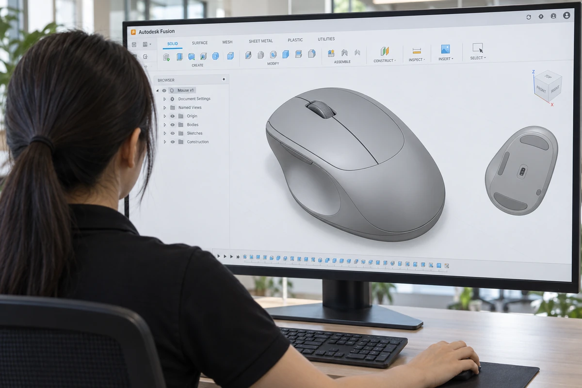
02 · CAD design
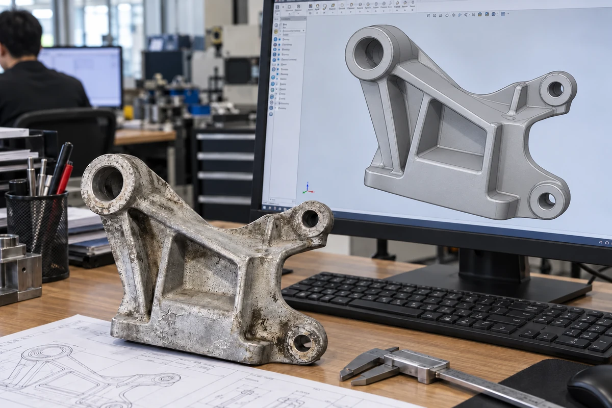
Work from the customer sketch alongside the CAD model. Refine the mounting holes, upright supports and camera fit before making prototypes.
Explore 3D design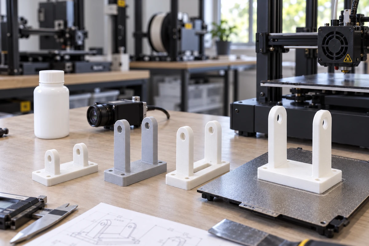
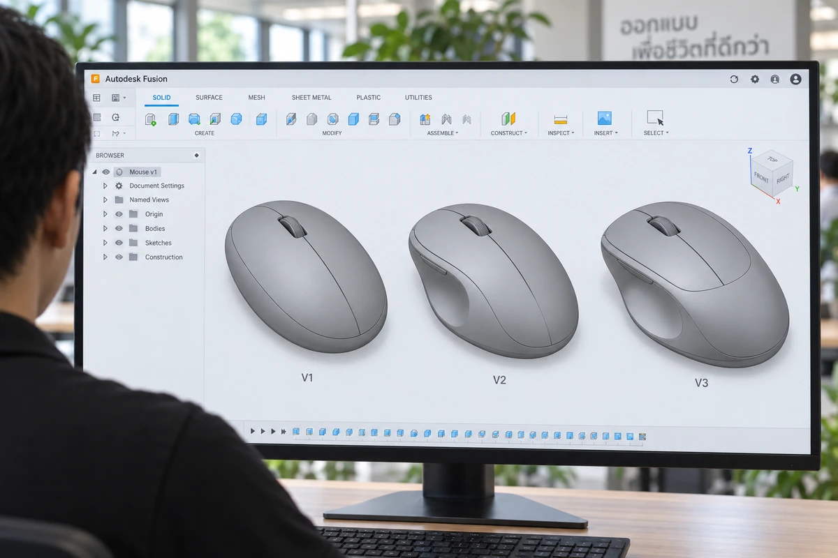
03 · Prototype variations
3D-print several bracket variations to compare height, stiffness and camera fit. Use the results to refine the final design.
Explore prototyping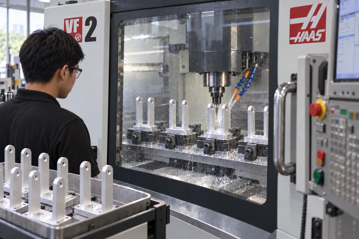
04 · CNC batch production
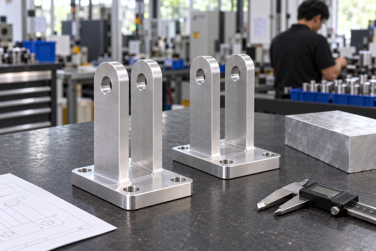
Machine the approved aluminium bracket in batches, using fixtures to hold the same design for repeat production and inspection.
Plan productionIllustrative project: the same camera bracket, bottle and inspection task throughout. Images illustrate the process and are not a named customer case study.
On the production line
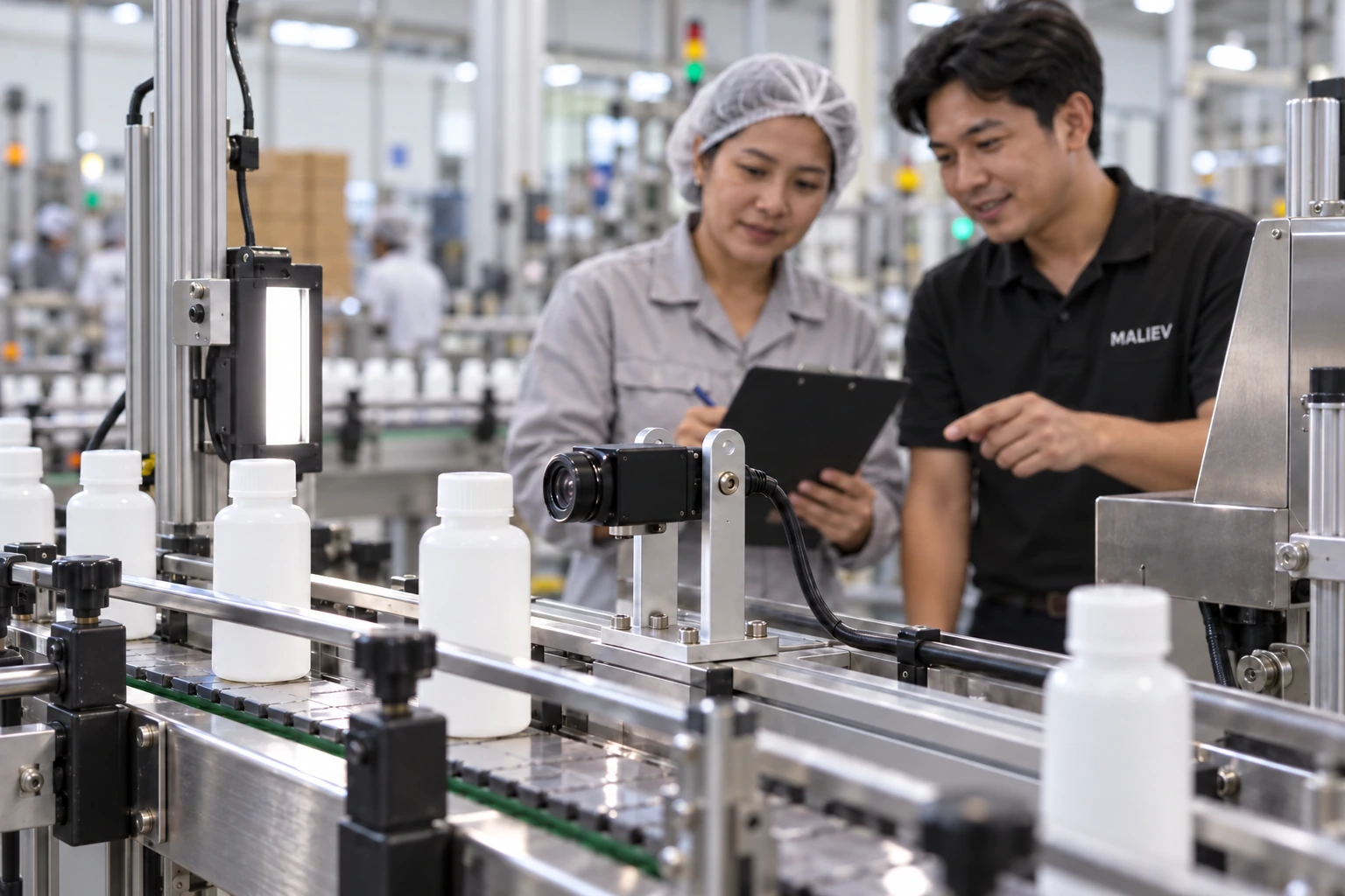
The final bracket holds the measurement camera beside the bottle conveyor. The mounting position, camera view and clearance come together in the application the customer sketched at the start.
Already have a part? Start there.
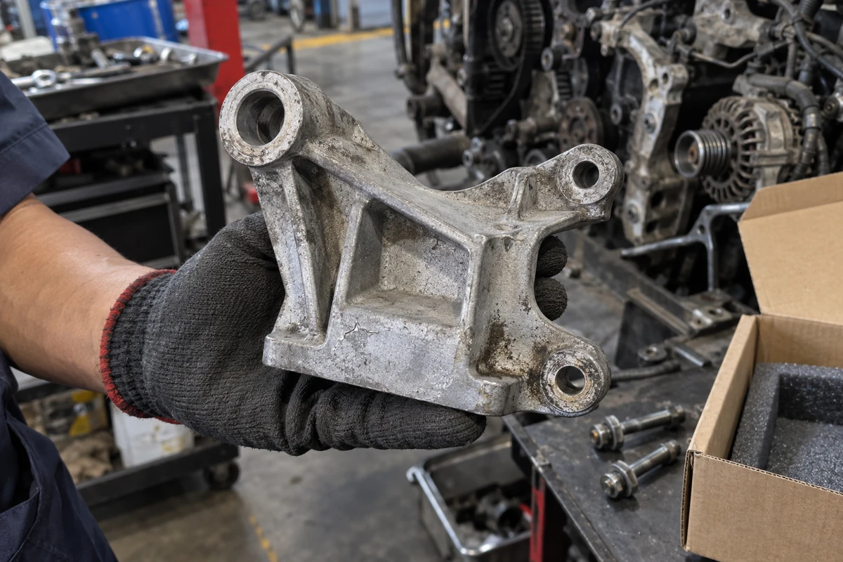
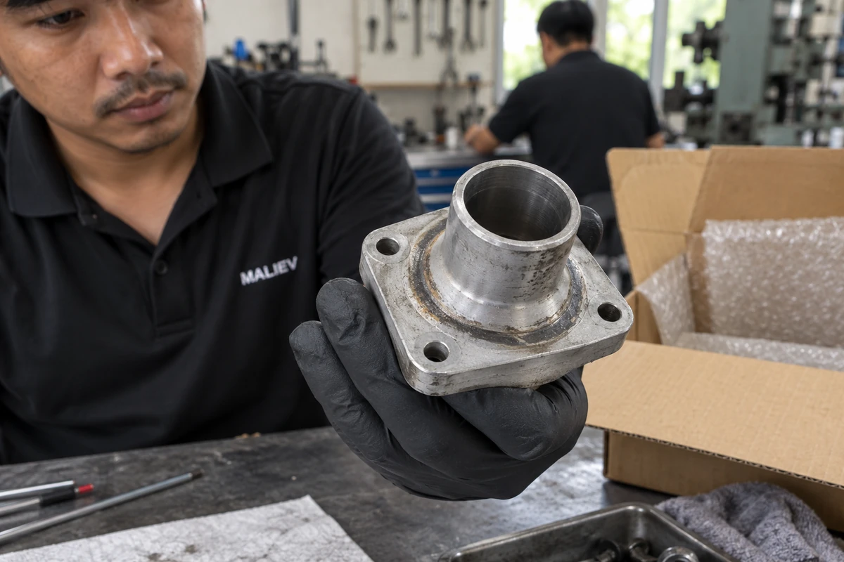
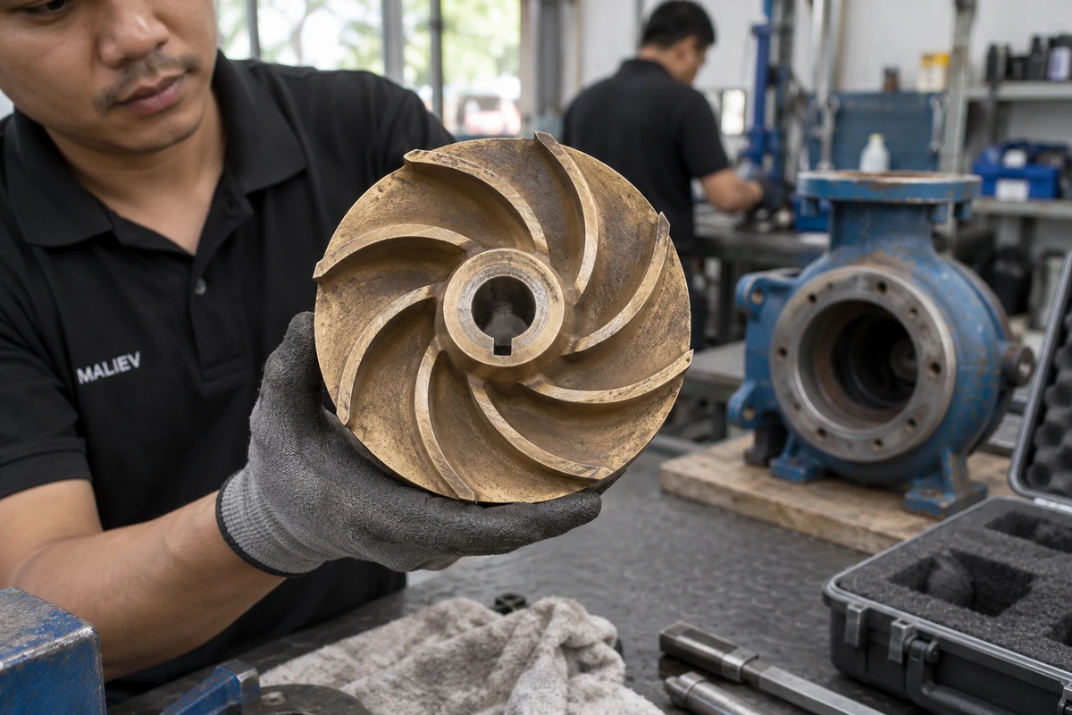
MALIEV also works from existing parts. Reverse engineering reconstructs a CAD design for replacement parts, functional improvements or further product development.
Share your sample and explain how it is used. We review the material, geometry and quantity together before choosing a manufacturing process.
Explore 3D scanningManufacturing capabilities
Explore the processes available for your material, geometry and production quantity.1 / 6
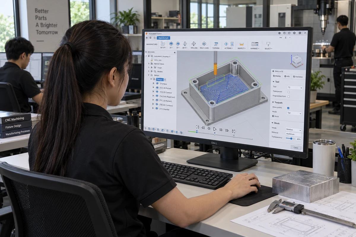
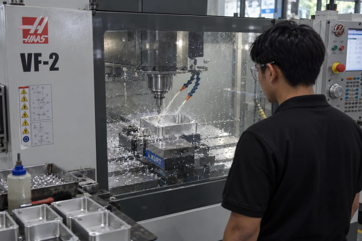
CNC machining
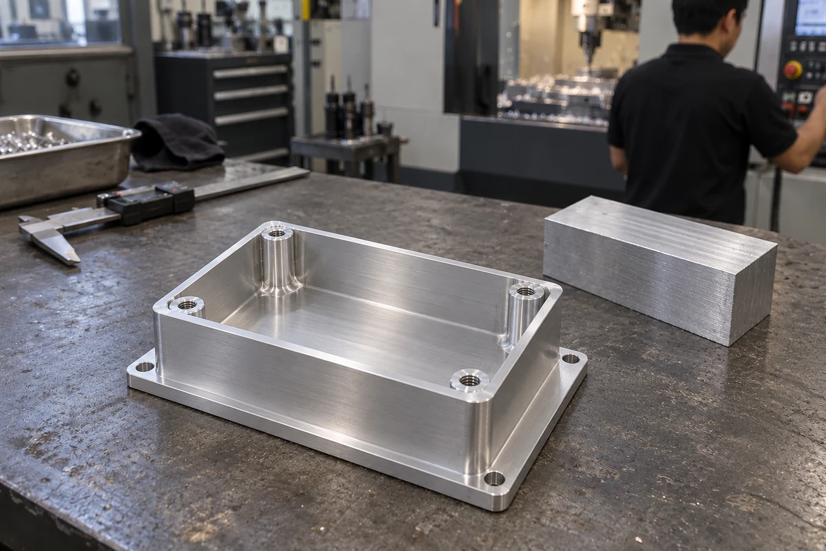
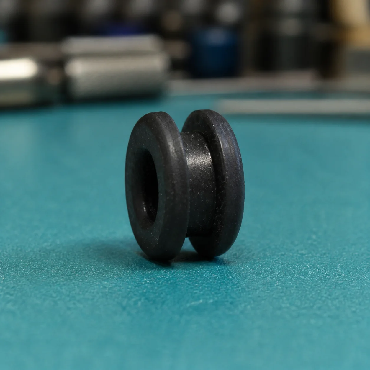
Machine metal and plastic parts from your drawings, with material, finish and inspection requirements agreed before production.
- Materials
- Metals and engineering plastics; confirm grade, stock and finish for each job.
- Files & requirements
- STEP/STP or IGES/IGS geometry, plus a PDF drawing for critical dimensions, tolerances, threads and fits.
- Production scope
- One-off parts through repeat batches, with machining access, setup and inspection reviewed before quotation.
3D printing
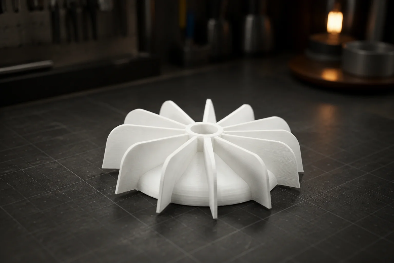
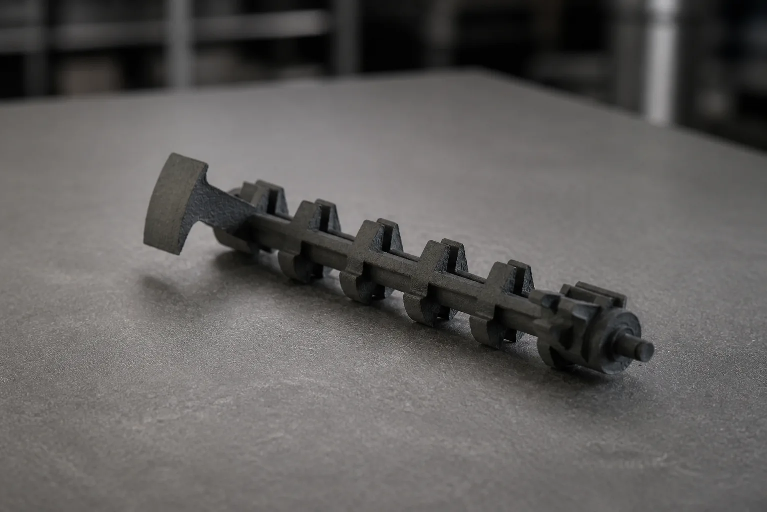
Build prototypes and functional parts to compare fit, form and design variations before committing to a production process.
- Technologies
- FDM and resin printing. MJF, SLS, SLM and DMLS require engineering review to confirm the project scope.
- Material selection
- Match stiffness, impact, heat and chemical exposure to the application; review layer direction, supports and finish.
- Files & next step
- STL, STEP, OBJ or 3MF. Compare printed variations for fit and function before approving the production design.
3D scanning
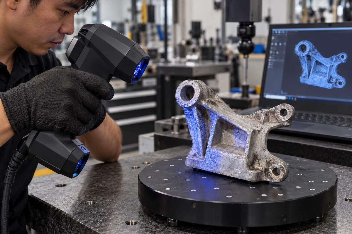
Capture the geometry of an existing part as a starting point for reverse engineering and CAD reconstruction.
- Capture
- Structured-light scanning, in-house or onsite after reviewing access, surface preparation and working conditions.
- Deliverables
- Scan-only work produces a triangular mesh such as STL. Editable CAD and 2D drawings are separately defined work.
- Engineering review
- Rebuild geometry or compare with nominal CAD. Agree critical features and reporting scope; wear may obscure the original design.
3D design
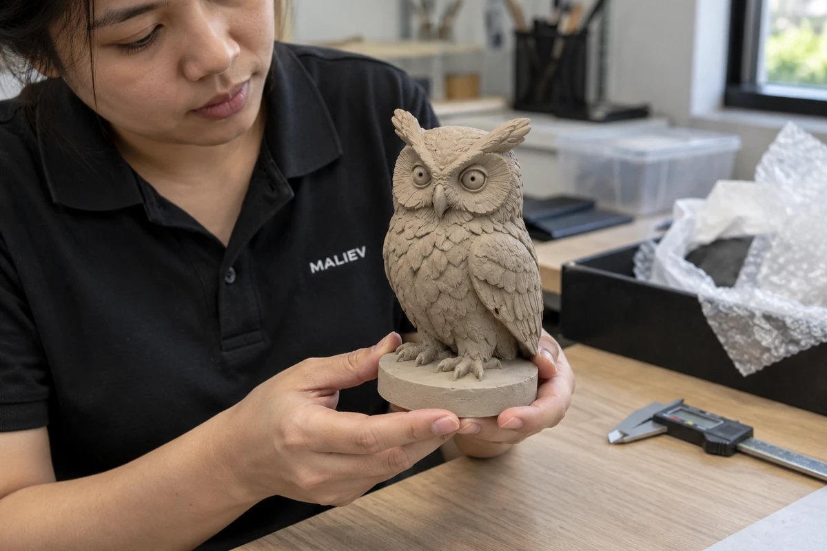
Develop CAD from a sketch, idea or existing part. Review assembly, material and manufacturability before making the first prototype.
- Starting information
- Sketches, reference photos, drawings, sample parts or scanned meshes, with intended use and critical interfaces.
- Design for manufacture
- Review material, tolerances, assembly, machining access, print orientation and mold strategy for the chosen process.
- Deliverables
- Agree CAD formats, STEP, STL and 2D drawings before modeling; validate the approved design with a prototype.
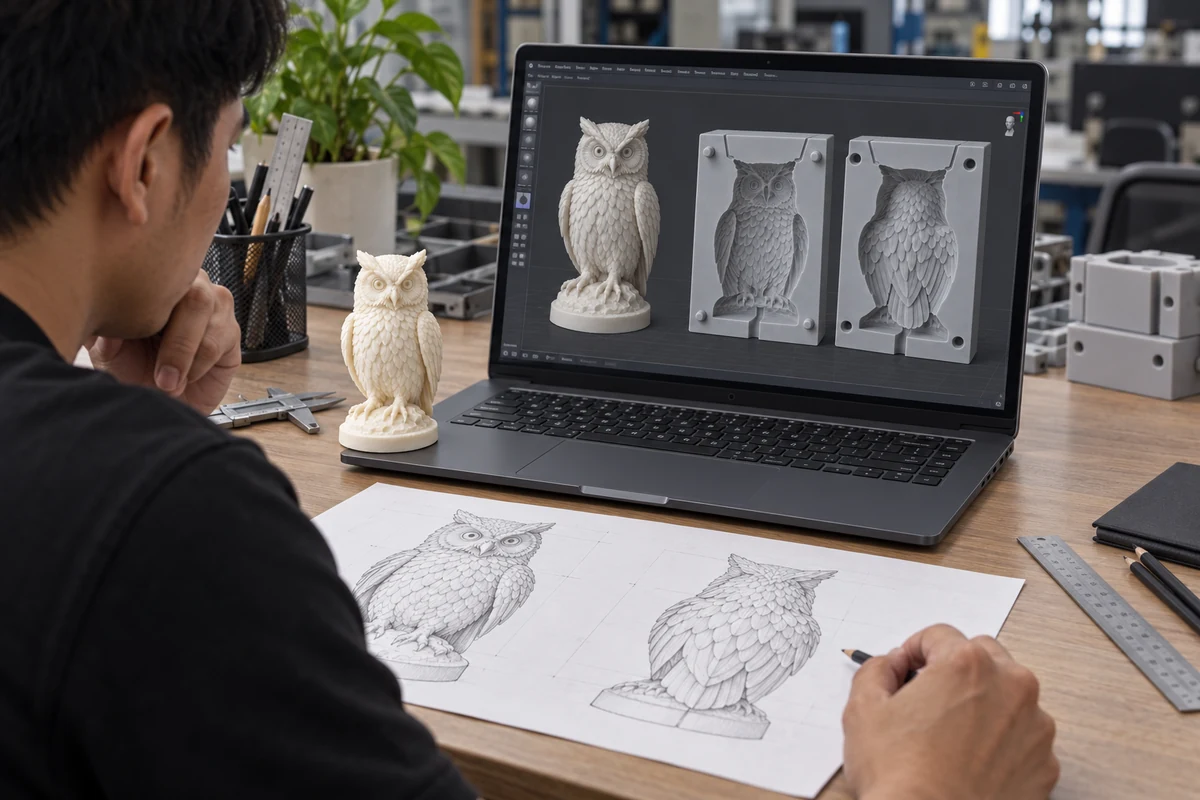
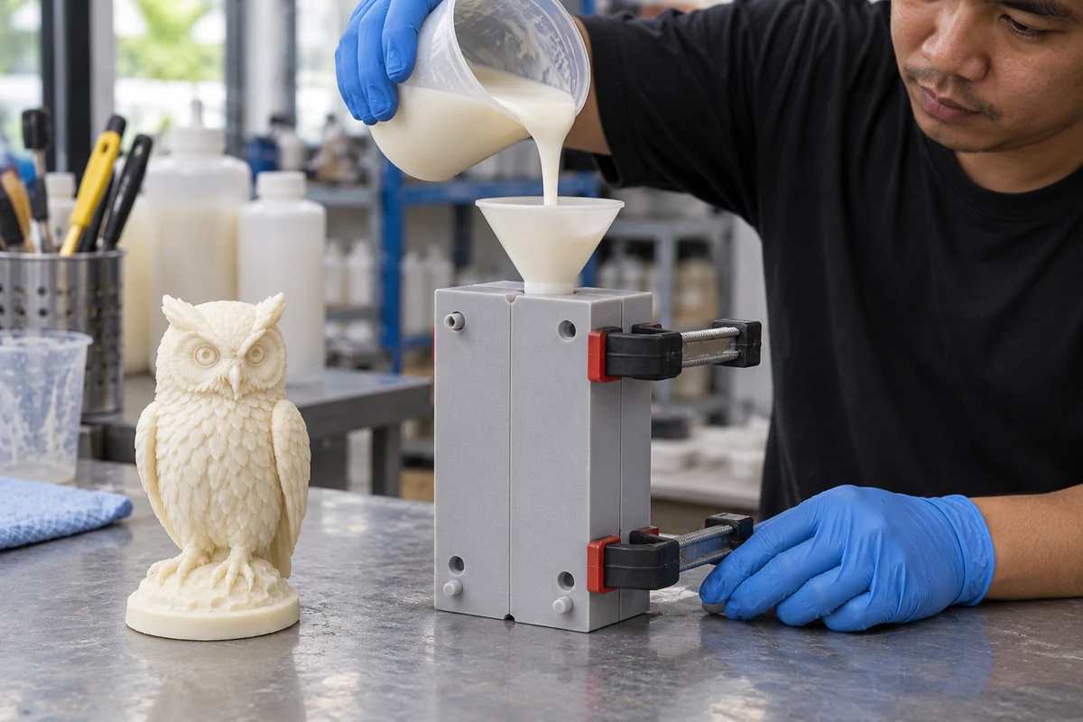
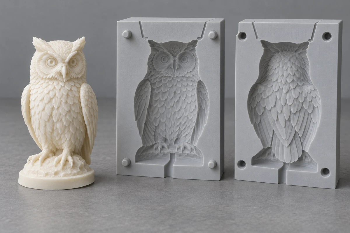
Silicone casting
Produce small quantities of silicone parts using a suitable mold, with material and surface requirements reviewed for the application.
- Process
- Cast liquid silicone in a 3D-printed mold for suitable prototypes and short runs.
- Mold review
- Review parting lines, vents, release, printed mold surface and silicone compatibility before pouring and curing.
- Specify the part
- Send CAD, quantity, hardness or flexibility, color, finish, inserts and intended use. Cure cycles and mold count affect the schedule.
Low-volume injection molding
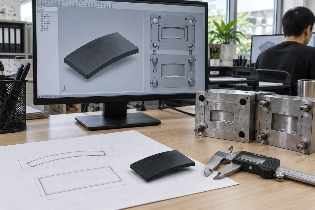
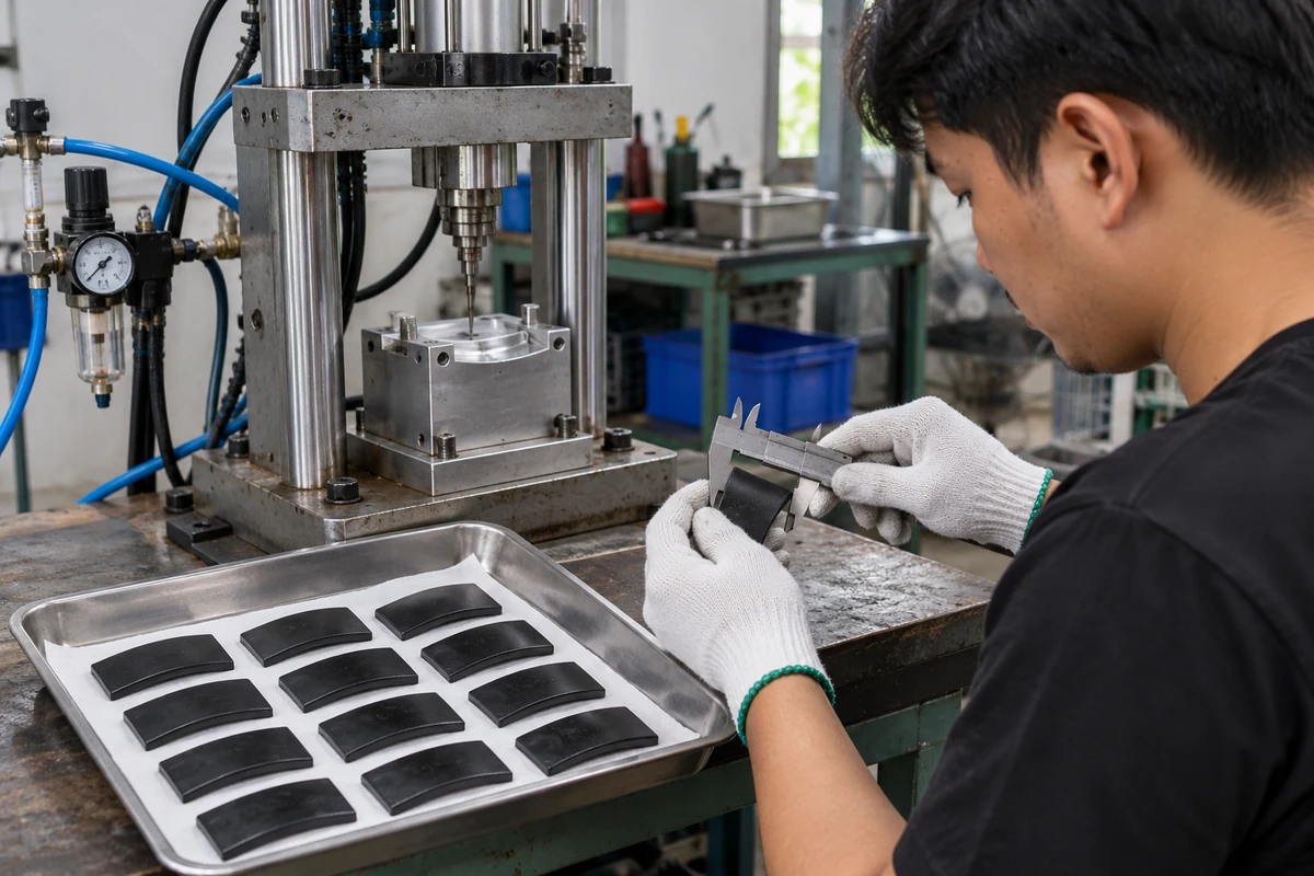
Review the part and tooling before production. Our pneumatic injection route supports the following limits.
- Technology & batch
- Pneumatic PIMM injection molding for pilot runs and repeat batches of up to 1,000 parts.
- Machine limits
- Up to 50 g per shot; plastic melting temperature up to 350 °C. Suitability depends on the part, resin and mold.
- Tooling & inspection
- Review an existing mold or scope a new tool. Confirm resin, geometry, finish, quantity and inspection requirements before production.
Before we quote
Clarify the technical requirements, project scope and confidentiality before quotation and manufacturing.Engineering requirements
Review intended use, critical dimensions and mating features using your CAD, drawing or physical sample. Identify missing information before choosing a production route.
Scope and deliverables
Clarify the process, material, finish, quantity and inspection scope so the quotation reflects the work and deliverables agreed together.
Project confidentiality
If your project requires an NDA, complete and sign the agreement before sending sensitive drawings, CAD files or samples.
View our NDAHave an idea, drawing or sample part?
Talk to us to review a development and manufacturing approach.