Raw capture
Point/mesh data for visualization, archiving, and downstream work.

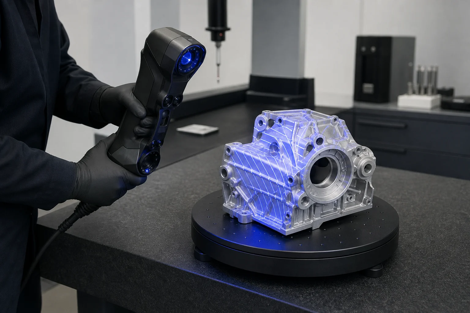
In-House & Onsite 3D Scanning
MALIEV provides reverse engineering in Thailand: capture real objects as digital geometry, rebuild editable CAD when needed, or compare a manufactured part with nominal CAD. We help define the correct deliverable before scanning begins.
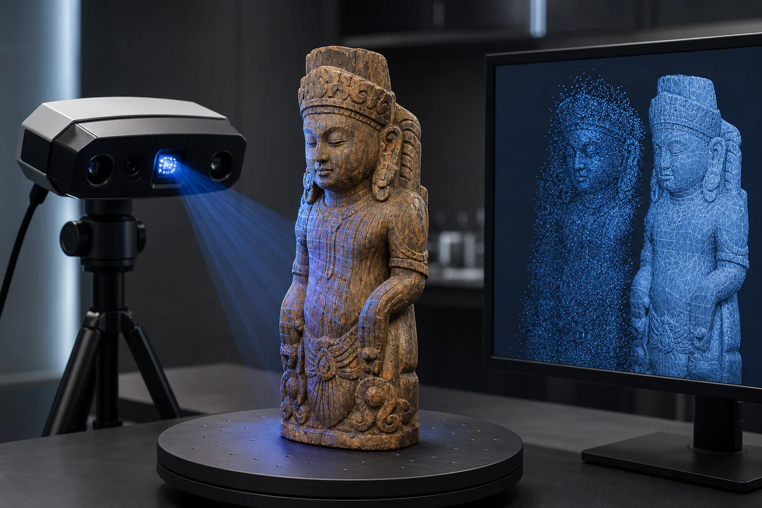
Point/mesh data for visualization, archiving, and downstream work.
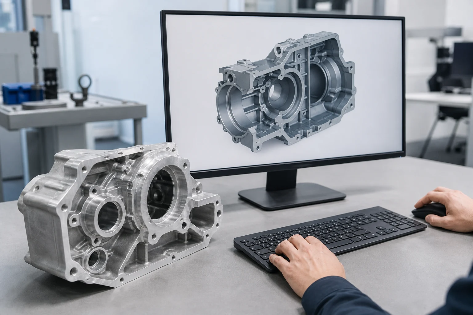
Reconstructed surfaces and features when editable CAD is required.
Compare scan data with nominal CAD to visualize differences.
For large, fixed, fragile, or impractical-to-transport objects.
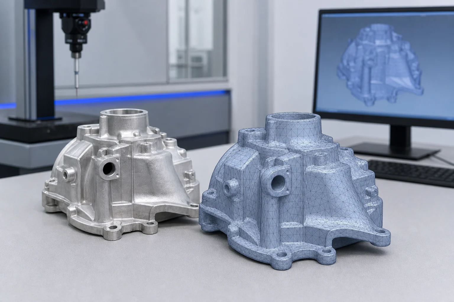
Compare two views of the same cast housing from a real project. Both use the same grey, viewpoint and framing. Triangle edges reveal the scan mesh; CAD edges outline the reconstructed surfaces.
Move the divider, or choose a full view. Focus the round handle to use the arrow keys.


Scan-only mesh and CAD reconstruction are separate deliverables. These images show visible geometry differences; they do not establish dimensional accuracy or a deviation inspection result.
Scanning captures the object first. The output becomes more useful as each stage adds cleanup, reconstruction, or comparison.
Start
We secure the workpiece, set up the scanner, and capture overlapping views before registering the scans into one coordinate space.
Stage 1
A mesh or point cloud for visualization, digital preservation, rendering, or your own downstream processing.
May still contain holes, noise, separate shells, or non-manifold edges.
Stage 2
Noise is removed, suitable holes are closed, and the mesh is checked for a watertight print-ready result when included in scope.
It is still triangular mesh—not editable CAD.
Stage 3
Features, interfaces, datums, and dimensions are reconstructed into editable geometry for engineering work.
Hidden design intent and assumptions need review.
Stage 4
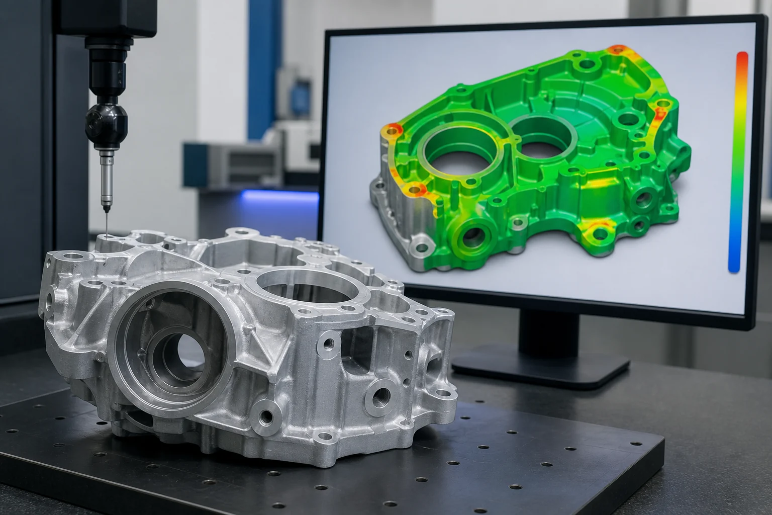
The scan is aligned to nominal CAD to show deformation, wear, or process variation with agreed views and limits.
Requires usable nominal CAD and an agreed alignment.
A scanner captures a mesh. Each next stage adds a different kind of processing and unlocks a different use. Choose the stopping point that matches the work you need to do next.
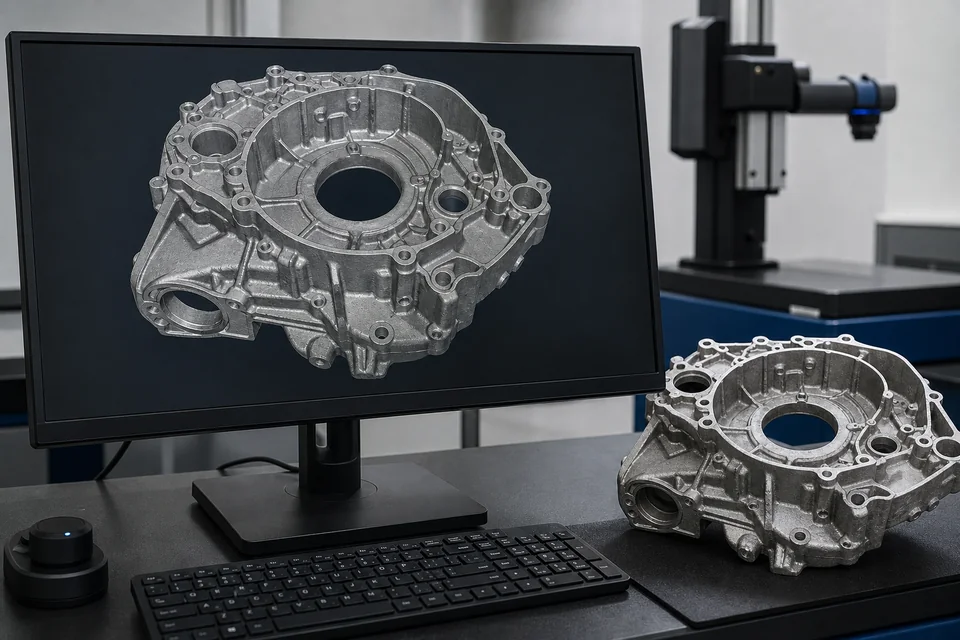
An aligned or lightly cleaned mesh for visualization, digital archiving, rendering, approximate measurement within the agreed scan capability, self-processing, or a reference for sculpting.
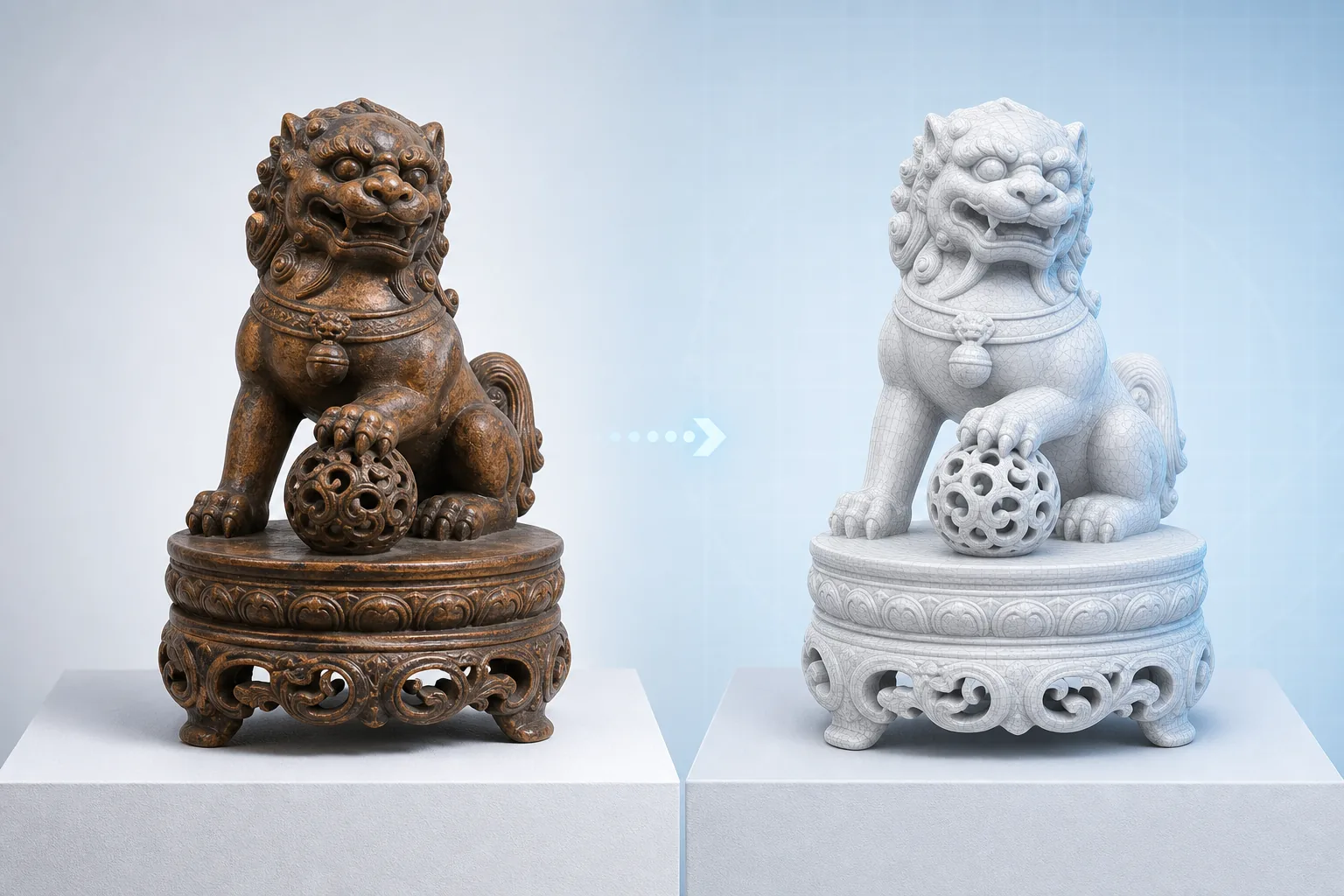
Noise and unrelated shells are removed, appropriate holes are closed, scale and orientation are checked, and the mesh is made watertight when that scope is agreed.
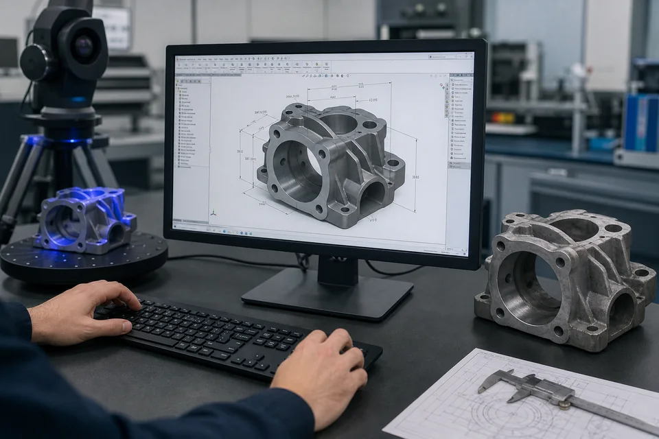
Features, datums, interfaces, dimensions, and design assumptions are reconstructed into editable CAD. A 2D DWG/DXF drawing can be added when the drawing scope is included.
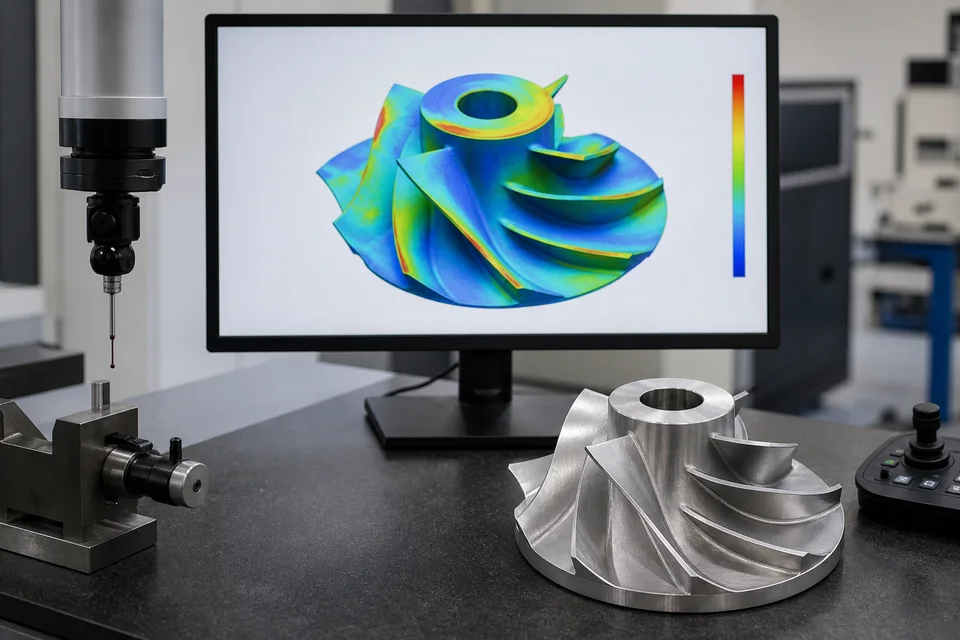
The scan is aligned to nominal CAD to show where the manufactured, worn, bent, or modified part differs, with agreed views, sections, limits, and reporting format.
* Availability depends on the capture method, source data, and agreed scope.
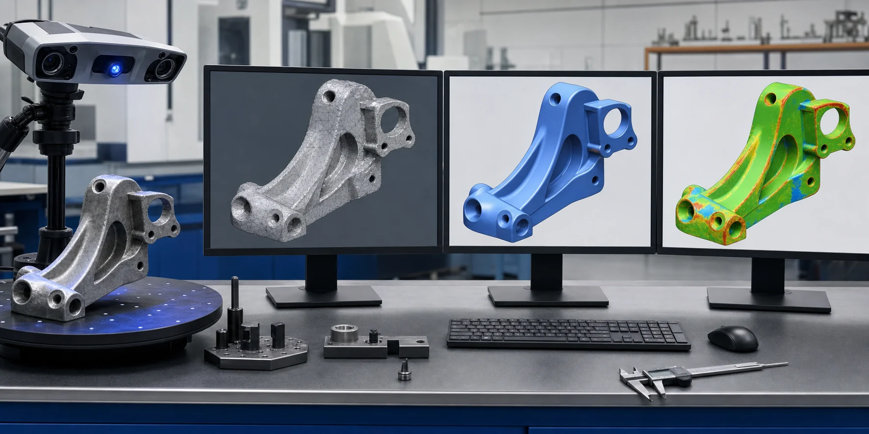
Each stage adds work and a different kind of information. Ordering only the stage you need avoids paying for unnecessary modeling while ensuring the output is usable.
Define purpose, critical areas, object size, surface, access, environment, target files, and whether nominal CAD exists.
Collect overlapping views with targets or geometry references, then align passes into a common coordinate system.
Remove unrelated data and noise, merge suitable regions, and fill only appropriate gaps without inventing critical hidden geometry.
Reconstruct agreed CAD features or align the scan with nominal CAD for deviation analysis and reporting.
Onsite scanning is useful when equipment, vehicles, architecture, tooling, sculptures, or assemblies are too large, fixed, fragile, valuable, or disruptive to transport.
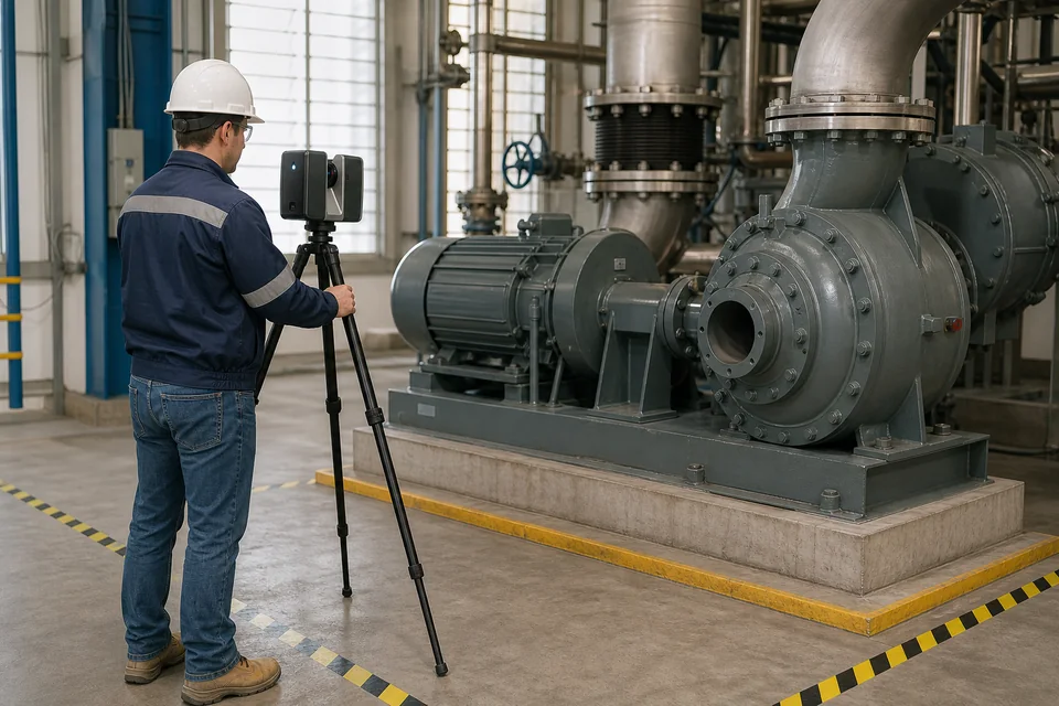
We need safe working clearance and line of sight around the subject. Barriers, height, confined spaces, live machinery, traffic, and production schedules affect feasibility.
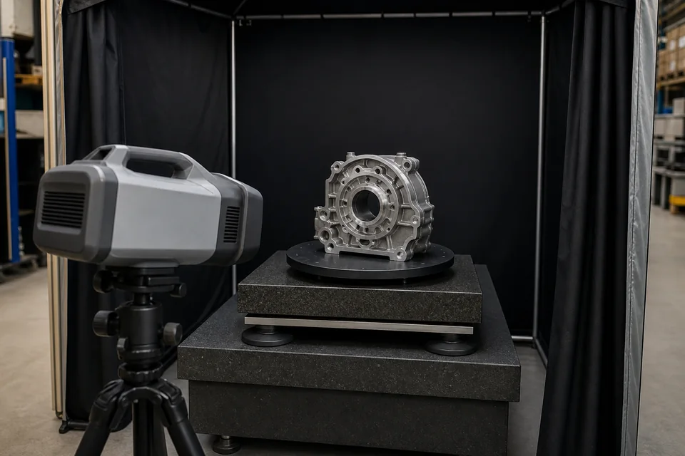
Changing sunlight, rain, dust, vibration, heat, wind, reflections, and object movement can reduce capture quality or require controls and repeat passes.
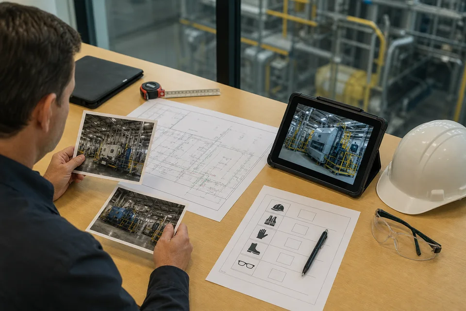
Share photos, dimensions, location, access restrictions, required PPE, operating conditions, target deliverables, and nominal CAD before scheduling.
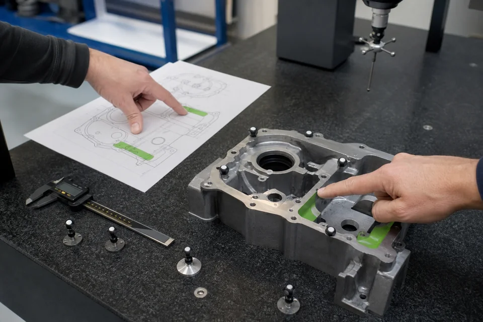
Identify critical dimensions, interfaces, areas of interest, intended file use, reference coordinate system, and acceptable exclusions.
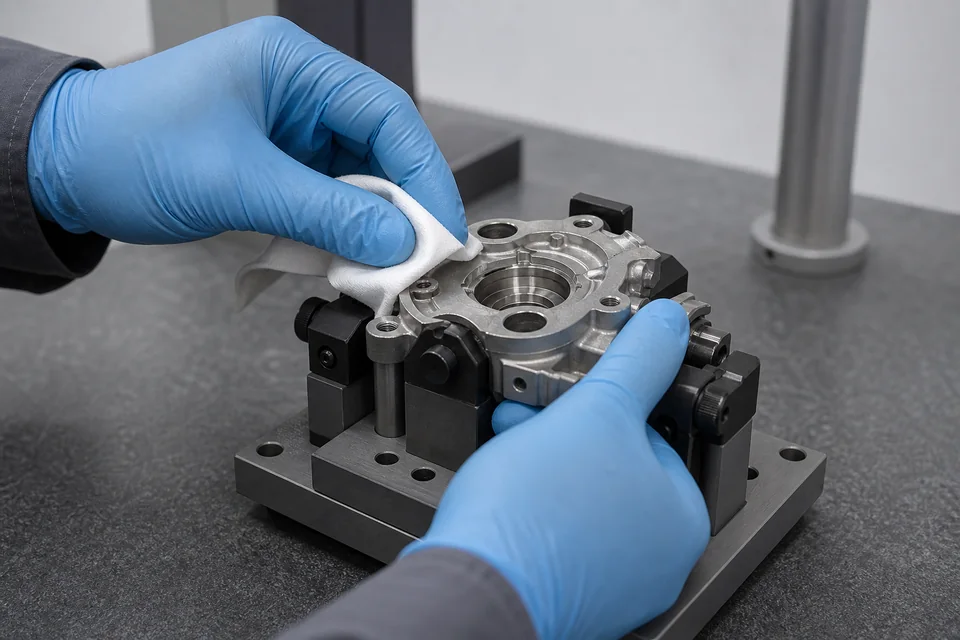
Remove loose dirt and unnecessary attachments where safe. Support flexible items, stop moving mechanisms, and maintain one stable shape during capture.
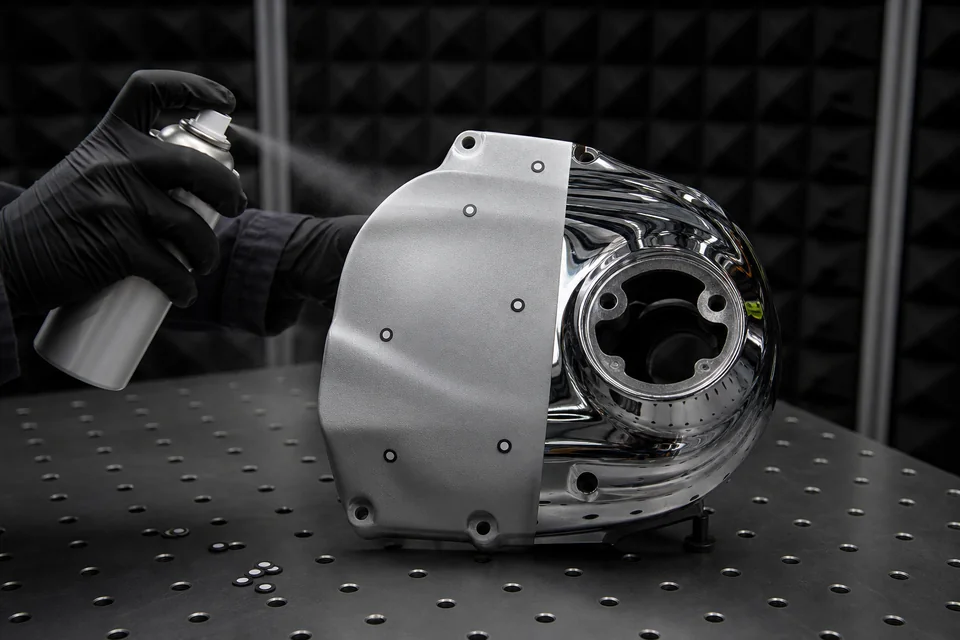
Reflective, transparent, translucent, or very dark surfaces may need controlled lighting, targets, or temporary removable scanning spray with owner approval.
Send what you have. We’ll help you work through the details before the visit.
Share a few photos, approximate size and location, and what you want to do with the file. Point out any important features.
Where safe, remove grease, dust, oil and loose covers. Tell us about hot, moving, fragile or shiny parts so we can agree on suitable preparation.
Arrange safe access around the part, a nearby 220V outlet and a site contact. Let us know about safety rules or access restrictions in advance.
Share the nominal CAD and drawing if available, with the revision and units. We’ll agree the alignment, deviation band, specific areas of interest and report format with you.
| Condition | What usually happens | Possible preparation |
|---|---|---|
| Matte, rigid, textured surfaces | Usually provide stable visual geometry for registration and capture. | Clean, expose critical areas, and keep the object still. |
| Shiny, mirror-like, transparent, or translucent | Light reflects or passes through, causing missing, distorted, or noisy data. | Controlled lighting, removable matte spray, targets, or another measurement method after review. |
| Deep holes, narrow gaps, undercuts, and internal passages | The scanner cannot capture surfaces it cannot see; shadowed geometry may remain incomplete. | Multiple angles, partial disassembly when approved, complementary measurement, or explicitly excluded regions. |
| Soft, flexible, moving, or hot objects | Shape changes between views and registration becomes unreliable or unsafe. | Stabilize safely, cool or stop equipment, define one operating state, or use a different capture strategy. |
| Very small edges, threads, engraving, or surface texture | Features below the practical sampling and optical limit may soften or disappear. | Identify critical features early so equipment, close-range capture, or complementary inspection can be evaluated. |
Use these guides to plan access, surface preparation, reverse engineering, and replacement-part reconstruction.
Check access, surface condition, reflective or transparent regions, reference targets, and the required output before the visit.
See why a triangular mesh is not automatically editable manufacturing CAD and when reconstruction is required.
Review what can be recovered from a physical sample, how wear affects design intent, and which manufacturing path may follow.
Read the replacement-part guide
After reconstruction, compare CNC machining for a defined machined part or custom manufacturing review when the production process still needs to be selected.
Raw 3D scanning with STL output starts at THB 2,500. Reverse-engineering output starts at THB 4,500. A deviation-analysis report adds THB 1,000. The final quotation depends on size, complexity, preparation, scan positions, site access, cleanup, alignment, and required deliverables.
Simple scanning work can be completed within the same day. Lead time increases with part complexity, surface preparation, the number of scan positions, mesh cleanup, reverse engineering, inspection, and reporting requirements.
Bring the example in the best available condition because the scan captures the geometry that is physically present. Broken parts can still be scanned, and missing or damaged areas can often be reconstructed or modified in the 3D model when sufficient reference geometry and design intent are available.
Our optical scanners can capture subjects ranging from small gears to a 6-metre private aircraft when access and conditions are suitable. Sculptures, art pieces, and a stationary human can also be scanned. Scope, achievable detail, setup, and deliverables are assessed for each subject.
Raw geometry is commonly delivered as STL. We can also provide OBJ with captured colour when the project and capture method support colour data. Reverse-engineering projects can add editable CAD deliverables such as STEP or IGES as agreed.
Scan-only normally delivers a triangular mesh such as STL. DWG is a 2D engineering drawing, so it needs a separate reverse-engineering and drafting stage. There is no fixed reduction because CAD/DWG effort depends on the geometry and drawing requirements; we can quote scan-only and CAD/DWG as separate line items.
The scanner's volumetric accuracy specification is 0.02 mm + 0.06 mm/m. Actual project results also depend on object size and surface, preparation, access, environment, scanner setup, alignment strategy, and the requested deliverable.
We cannot perform optical 3D scanning outdoors under direct sunlight because sunlight overwhelms the projected light used by this scanning technology. We also do not offer whole-building or whole-factory scanning because we do not have a LiDAR 3D scanner. Onsite scanning of suitable parts and equipment remains available in controlled lighting.
No. The scanner needs line of sight and a stable optical response. Transparent, mirror-like, moving, very hot, inaccessible, internal, extremely small, or unsafe subjects may need preparation, partial results, another method, or may not be feasible.
An STL is normally a triangular surface mesh. It can be measured and edited with mesh tools, but it does not contain the parametric features, sketches, dimensions, and design intent of a native CAD model. Reverse engineering adds that reconstruction work.
No. It reconstructs an engineering model from visible, measurable geometry and agreed design assumptions. Wear, damage, inaccessible areas, deformation, casting variation, and unknown original intent require judgment and may not reproduce original feature history.
Usually the physical part, usable nominal CAD, a defined alignment method, critical regions, reporting needs, and an agreed interpretation of color limits. The result shows differences relative to that alignment; it is not automatically certified dimensional inspection.
Yes. We provide onsite scanning when a part is very large, cannot be disassembled, or cannot reasonably be shipped, subject to feasibility, access, safety, lighting, working space, and schedule. Travel is quoted by distance and project scope. Send photos, approximate dimensions, location, restrictions, and required deliverables for planning.
Use these starting points to choose a service. The final quotation is confirmed after we review geometry, material, quantity, finish, tolerances, and delivery requirements.
A scan mesh for visual reference, inspection, or downstream preparation.
Starts at approximately THB 2,500A usable CAD reconstruction built from the physical part and agreed deliverables.
Starts at approximately THB 4,500Travel, access, object size, and inspection requirements affect the quotation.
Quoted after site reviewPrices are planning references, not a binding offer. We will confirm the scope, tax, delivery, and any revision or finishing work before production.
We accept customer files throughout Thailand and ship completed parts nationwide by parcel.
For workshop consultation, drop-off, or collection in Pak Kret, notify us by phone or LINE Official Account, or schedule an appointment before visiting.
Onsite work is available for applicable services after project review; travel is quoted by distance and project scope.
Maliev Co., Ltd.
Business hours
Monday-Friday: 09:00-18:00
Saturday-Sunday: Closed
Share photos, size, location, surface condition, critical areas, nominal CAD, and target files. We will help define an appropriate scope.